制造商零件编号 15083
SPARKFUN QWIIC TWIST - RGB ROTAR
SparkFun Electronics
License: See Original Project
This guide will walk you through getting the SparkFun Qwiic Twist RGB rotary encoder and the Adafruit 0.91” OLED display to work with the XRP kit's drive_examples.py file. The best part? Both boards are Qwiic and Stemma QT compatible, so no soldering is required, which means you can get started with development quickly!
With this guide, you can load multiple programs ahead of time and use the encoder to select which program to run instead of having to load them individually from the computer each time you want to switch programs. This opens endless possibilities! You can run base programs or set up multiple autonomous programs. It's like having your own robot team, similar to the First Robotics FTC program! You can easily change which side your robot will be placed on the field, whether they are the left or right robot on your alliance. Just turn the encoder to select which program to run and let it do its job.
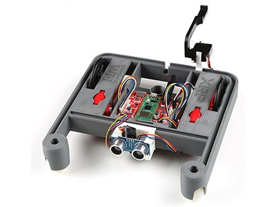
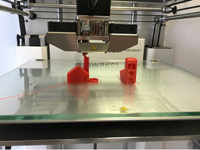
Installing hardware via a Qwiic connector is a very easy process. I used two Qwiic cables to daisy-chain the OLED display to the encoder, which I then connected to the XRP’s Qwiic connector. I modified the file for the line-follower sensor mount in Fusion 360 to create snap-fit mounts for these two boards. The STL files for these can be found here: https://www.thingiverse.com/thing:6230756. These mounts snap into the rail system on the robot, so they are very easy to move around to fit new components as needed.
XRP Qwiic Connections and Mounting brackets
OLED Screen mount top view
Qwiic Twist RGB Encoder Mount top view
Required Libraries
To get the screen working, I used this GitHub repository (https://github.com/jdhxyy/ssd1306py-micropython), which appears to be a fork of Adafruit’s original MicroPython repo that has since been deprecated. The page is in Chinese. However, using Google Translate I was able to confirm that the code would work for this project. To install the library, open the ssd1306.py file in the ssd1306py folder and then click the Copy Raw data icon in the top right corner of the preview. Then, in the XRP Code Editor, verify you are connected to your XRP, select the File dropdown at the top left of the blue toolbar, and select New File. Click the Micro Python button on the right side of the screen, click into the main code body, and paste the copied code from the GitHub repository. With the code pasted into the file, click File, and select Save to XRP. A Choose a Directory and Name popup will appear. Hover your mouse over the lib folder and right-click. Select the New Folder option when it appears, type ssd1306 into the new folder name popup, and input ssd1306.py as the file name. Once this is saved, the first new library is installed.
Follow the same process to Copy the quiic_twist.py file from this GitHub repository (https://github.com/rdagger/micropython-quiic-twist). Rename the folder and the file to qwiic_twist.py and the folder to micropython_qwiic_twist (This will come in handy to know when looking at the examples below). I also saved the demo_polling.py example into another new folder called test sketches on the XRP. I used these files for testing to see how the Qwiic Twist encoder works and further understand how it is coded.
Testing the Encoder
The first test I did was the qwiic_twist_polling_demo (renamed test sketch from the quiic twist repository) which uses the RGB encoder. While looking at the top of the code, I noticed that the sleep function was loaded from the time library, and the I2C and Pin functions were loaded from the machine library. The next thing I noticed was that the code was trying to load the Encoder function from the quiic twist library. Recalling that I renamed the file to qwiic_twist and placed it in the micropython_qwiic_twist folder, I made updates to the code to match. Once I changed the name of the folder and file in the code to match where the libraries and functions are located, I was able to use the following code to load them.
from time import sleep
from machine import I2C, Pin
from micropython_qwiic_twist.qwiic_twist import Encoder
The next part of the code calls out what I2C pins the Qwiic Twist board is connected to. Using the SparkFun XRP Robot Controller Hardware Overview page, I updated the code to pins 18 for the Data signal (SDA), and pin 19 for the clock signal(SCL). Having modified the pins in the code, I looked further down and saw a line that set the count limit for the encoder's detents. For this demo, I left it set to 12, but I was fairly certain that this was one of the ways I set the encoder's limits.
i2c = I2C(1, freq=400000, scl=Pin(19), sda=Pin(18))  # Pico I2C bus 1
encoder = Encoder(i2c)
encoder.set_limit(12)  # Set count limit to 12 detents
I then noticed that the code defined a function called test. This function sets the color of the encoder to cyan by using a color combo of 0, 255, and 255. These three numbers represent the red, green, and blue components of the color, with 0 being the minimum intensity and 255 being the maximum intensity.
The code then proceeds to obtain the encoder firmware version and the limit that was set earlier. After printing this information to the Shell, it enters a try-except-finally section of code. These sections are used to test a piece of code, and if an exception occurs, the code in the except clause will be executed. The finally section of this code block is what the code does after the try or except code has been executed completely. In the try section, a while True statement is used. Within this while True statement, the code checks if the encoder has been clicked and sets the clicked variable to the correct Boolean value, either True or False. It then sets the moved Boolean variable to either true or false depending on whether the encoder has moved. Next, it checks if either moved or clicked has been set to true and, if so, it sets the count variable to the number of clicks the encoder has moved. This is followed by the difference detected by the code. The dif variable is then set to the number of the difference from the last starting spot. After this is completed, the is_pressed Boolean variable is set to true if the encoder has been pressed in this cycle. Finally, the code prints out the information if the encoder has moved and if it was clicked in the Shell. It also prints out the difference in the move.
def test():
    """Test code."""


    # Set the knob color to cyan
    encoder.set_color(0, 255, 255)


    version = encoder.get_version()
    print("Firmware version: {}".format(version))
    print("Limit: {}".format(encoder.get_limit()))


    try:
        while True:
            clicked = encoder.has_clicked()
            moved = encoder.has_moved()
            if moved or clicked:
                count = encoder.get_count()
                diff = encoder.get_diff(True)
                is_pressed = encoder.is_pressed()
                print()
                print("Encoder moved: {}, Button clicked: {}".format(moved,
                                                                     clicked))
                print("Tick count: {}, Difference: {}".format(count,
                                                              diff))
                print("Button is pressed: {}".format(is_pressed))
            sleep(.3)
    except KeyboardInterrupt:
        print("\nCtrl-C pressed to exit.")
    finally:
        encoder.set_color(0, 0, 0)
The final step in this sketch is to execute the test function, which is indicated by the following line of code.
test()
I pressed the Run button at the top left of the screen to test the encoder, and it worked as expected. To further test my theory on the encoder's limits, I changed the encoder set limit to 8, as that will be the number of programs I will be choosing from in the final code. After hitting run again, the count went to 7 and then rolled back over to 0, which is exactly what we need for the final program.
Testing the Display
The next thing to test was the LCD screen. After looking through the examples in the description of the main page of the ssd1306py GitHub repository, I decided to try to create a test sketch to print some words on the screen.
To get started, I clicked on File and then New File. I copied the code for the I2C and Pin imports from the Machine library and pasted it below the XRPLib line. Next, I included the ssd1306 library that I had saved previously. Finally, just in case I needed to use a time feature, I imported the time library.
from XRPLib.defaults import *
from machine import Pin,I2C
from ssd1306 import ssd1306
import time
To get the screen to work, we must call out the i2c connections. Looking through the library, I found a line that calls out the I2C connection.
i2c = machine.I2C(i2c, scl=machine.Pin(scl), sda=machine.Pin(sda)
And changed the (scl) to 19 and the (sda) to 18.
i2c = machine.I2C(i2c, scl=machine.Pin(19), sda=machine.Pin(18)
The next thing to set up is the OLED definition. A couple of lines lower in the library code, it calls out where the name of the OLED screen is set to oled.
oled = ssd1306.SSD1306_I2C(_width, _height, _i2c)
I set the width to 128, the height to 32, and change _i2c to i2c.
oled = ssd1306.SSD1306_I2C(128,32,i2c)
Next, it is time to test some text on the screen.
I created a while true loop for this code to run in. Then, I set up the first line of code. To call the OLED and create a line of text, I must call oled.text followed by an open parenthesis, the text inside the parentheses, a comma, the X coordinate, another comma, the Y coordinate, and a closing parenthesis. This is what it looks like written out:
oled.text ('Test Text',0,0)
then, to get this text to show up we will first need to call out the oled.show command on the line following the text line.
oled.show()
Click the Run button and you should see something similar to this:
Next, let’s see how the next row of text will fit by adding another row of text to the screen between the row one text and the show command.
oled.text ('Row 2 Test Text',0,2)
Click the "Run" button and observe the results. As you may have noticed, there is a problem with the text. The text in Row 2 is overlapping the first line of text.
Let’s try spacing it out a bit more by changing the Y-axis to 5 instead of 2.
oled.text ('Row 2 Test Text',0,5)
The results are still not satisfactory. Let's try increasing the spacing by changing the Y-axis to 10.
oled.text ('Row 2 Test Text',0,10)
This looks good. Now, let's add another line of text. Add the following line of code and remember to move the Y spacing down by another 10.
oled.text ('Row 3 Test Text',0,20)
Three lines of text look good. Let's see what happens when we add a fourth line.
oled.text ('Row 4 Test Text',0,30)
As you can see, the fourth line is mostly obscured. Three lines at this font size are probably the maximum we can fit on the screen, but three lines should suffice for this project.
The Drive Examples
Now that we have both the screen and the encoder working separately, let’s take a look at the drive examples test code to see what it does.
from XRPLib.defaults import *
import time
The first part of the code loads the XRPLib and all functions in that library. Then the time library is imported into the sketch.
After these two libraries have been loaded, the program has 8 different functions that are called out in the program that cause different actions with the robot. Let’s walk through each of those functions.
# drive straight for a set time period (default 1 second)
def drive_straight(drive_time: float = 1):
    drivetrain.set_effort(0.8, 0.8)
    time.sleep(drive_time)
    drivetrain.stop()
The drive_straight program does just as it says for a specified time. When calling the function, you could change the drive straight duration by adding a number between the parentheses that calls out the number of seconds. As you will see in the next few functions, the time is used to be a delay from when the program starts until it stops. The drivetrain.stop() function is used to stop the robot and wait for the next command.
Drive Straight function
# drive at a slight counterclockwise arc for a set time period (default 1 second)
def arc_turn(turn_time: float = 1):
    drivetrain.set_effort(0.5, 0.8)
    time.sleep(turn_time)
    drivetrain.stop()
The second function is the arc turn. This gives each of the wheels a little different effort causing the robot to travel in an arc. By changing the effort of each wheel, it is possible to manipulate the size of the arc that is made.
Arc Turn Function
# turn CCW at a point for a set time period (default 1 second)
def point_turn(turn_time: float = 1):
    drivetrain.set_effort(-0.8, 0.8)
    time.sleep(turn_time)
    drivetrain.stop()
The third function is a point turn. This is completed by setting the effort so that both wheels are traveling in opposite directions at the same speed causing the robot to rotate on a point.
Point Turn Function
# pivot turn around the left wheel for a set time period (default 1 second)
def swing_turn(turn_time: float = 1):
    drivetrain.set_effort(0, 0.8)
    time.sleep(turn_time)
    drivetrain.stop()
The fourth function is a swing turn, where only one of the wheels will have the motor on causing the robot to pivot on the other.
Swing turn Function
# Driving in a circle by setting a difference in motor efforts
def circle():
    while True:
        drivetrain.set_effort(0.8, 1)
The fifth function is the circle function. The size of the circle can be changed by changing the effort of each wheel. With 0.8 effort set for the Left wheel and 1 for the right, it makes a large circle.
Circle function
# Follow the perimeter of a square with variable sidelength
def square(sidelength):
    for sides in range(4):
        drivetrain.straight(sidelength, 0.8)
        drivetrain.turn(90)
    # Alternatively:
    # polygon(sidelength, 4)
The sixth function is the square function. When this function is called, the user can enter the length of the sides of the square which is in Centimeters.
Square Function
# Follow the perimeter of an arbitrary polygon with variable side length and number of sides
# Side length in centimeters
def polygon(side_length, number_of_sides):
    for s in range(number_of_sides):
        drivetrain.straight(side_length)
        drivetrain.turn(360/number_of_sides)
The seventh function is polygon. When this is called, the user needs to enter the length of the side, again in centimeters, and the number of sides of the polygon. As you can see in the example below, the parameters sent with the command were for an 8-sided polygon with a side length of 4 cm.
Polygon Function
# A slightly longer example program showing how a robot may follow a simple path
def test_drive():
    print("Driving forward 25cm")
    drivetrain.straight(25, 0.8)


    time.sleep(1)


    print("turn 90 degrees right")
    drivetrain.turn(90,0.8)


    time.sleep(1)


    print("turn 90 degrees left by setting speed negative")
    drivetrain.turn(90, -0.8)


    time.sleep(1)


    print("drive backwards 25 cm by setting distance negative")
    # There is no difference between setting speed or distance negative, both work
    drivetrain.straight(-25,0.8)
The eighth and last function is a test drive function. This function has the robot drive forward, turn 90 degrees left, pivot back 90 degrees right, and reverse back to the original starting position. This function is a good example of how to put together a function that combines several steps into a single function.
Test drive function
Now that we have seen the three examples that we will combine into the final code, let’s start putting that code together.
Putting the Pieces Together
To begin with the final code, open the drive_examples file, click on the file button, and save it to the XRP. Give the file a name that you will remember and then save it.
I would recommend adding a note with the GitHub repo addresses next, so that you can easily refer back to them if necessary. I typically like to do this at the very top of the code for easy access.
# I2C screen repo - ssd1306py-micropython/ssd1306py/ssd1306.py at master https://github.com/jdhxyy/ssd1306py-micropython
#qwiic twist github repo - https://github.com/rdagger/micropython-quiic-twist
The hash mark (#) at the beginning of a line indicates that it is a comment. Comments are ignored by the XRP, but they can be helpful for explaining what the code is doing. Commenting out lines of code can be useful for debugging a program. To do this, simply place a hash mark at the beginning of the line you want to comment out. I used this technique throughout the development of this code to ensure that each step was working before moving on.
Next, I will import all the libraries and functions needed for the new combined code.
from XRPLib.defaults import *
import time
from time import sleep
from machine import I2C, Pin
from micropython_qwiic_twist.qwiic_twist import Encoder
from ssd1306 import ssd1306
After adding all the libraries, we will need to set up the I2C line and the encoder. The encoder set limit will need to be set to 8, and the OLED screen will need to be set up. I copied the first three lines below from the encoder code, and the last line is from the OLED test code. Since the encoder already calls out the I2C line, we do not need to call it out again from the OLED code.
i2c = I2C(1, freq=400000, scl=Pin(19), sda=Pin(18))  # Pico I2C bus 1
encoder = Encoder(i2c)
encoder.set_limit(8)  # Set count limit to 12 detents
oled = ssd1306.SSD1306_I2C(128,32,i2c)
Next up, we're gonna print a message on the OLED screen that says "Turn the encoder to select the program." To make sure it all fits on the screen, I'm gonna split it into two lines: "Turn encoder to" on the first line, and "select program" on the second line. Finally, we'll add the oled.show command to make it appear on the screen.
oled.text('Turn enoder to',0,0)
oled.text('select program',0,10)
oled.show()
After that, I created a variable to keep track of the current count. This will be clarified later when we reach the test function.
current_count = 0
Since the drive_examples code has been saved, the next piece of code should already be loaded into the file.
# drive straight for a set time period (defualt 1 second)
def drive_straight(drive_time: float = 1):
    drivetrain.set_effort(0.8, 0.8)
    time.sleep(drive_time)
    drivetrain.stop()


# drive at a slight counterclockwise arc for a set time period (default 1 second)
def arc_turn(turn_time: float = 1):
    drivetrain.set_effort(0.5, 0.8)
    time.sleep(turn_time)
    drivetrain.stop()


# turn CCW at a point for a set time period (default 1 second)
def point_turn(turn_time: float = 1):
    drivetrain.set_effort(-0.8, 0.8)
    time.sleep(turn_time)
    drivetrain.stop()


# pivot turn around the left wheel for a set time period (default 1 second)
def swing_turn(turn_time: float = 1):
    drivetrain.set_effort(0, 0.8)
    time.sleep(turn_time)
    drivetrain.stop()


# Driving in a circle by setting a difference in motor efforts
def circle(turn_time: float = 1):
#    while True:
        drivetrain.set_effort(0.8, 1)
        time.sleep(turn_time)
        drivetrain.stop()


# Follow the perimeter of a square with variable sidelength
def square(sidelength):
    for sides in range(4):
        drivetrain.straight(sidelength, 0.8)
        drivetrain.turn(90)
    # Alternatively:
    # polygon(sidelength, 4)


# Follow the perimeter of an arbitrary polygon with variable side length and number of sides
# Side length in centimeters
def polygon(side_length, number_of_sides):
    for s in range(number_of_sides):
        drivetrain.straight(side_length)
        drivetrain.turn(360/number_of_sides)


# A slightly longer example program showing how a robot may follow a simple path
def test_drive():
    print("Driving forward 25cm")
    drivetrain.straight(25, 0.8)


    time.sleep(1)


    print("turn 90 degrees right")
    drivetrain.turn(90,0.8)


    time.sleep(1)


    print("turn 90 degrees left by setting speed negative")
    drivetrain.turn(90, -0.8)


    time.sleep(1)


    print("drive backwards 25 cm by setting distance negative")
    # There is no difference between setting speed or distance negative, both work
    drivetrain.straight(-25,0.8)
We will now begin constructing the code that will bring all of these examples together. Begin by copying the test function from the qwiic_twist_polling demo and pasting it just below the test_drive example.
The first modification made to the code is to change the original encoder set color to green. This was done so that the program would change to red when it is running. However, you are free to change this color if you prefer.
encoder.set_color(0, 255, 0)
After the "If moved or clicked" line is executed, the code assigns a value to the "count" variable. I added a line that assigns the value of the "count" variable to the "current_count" variable.
if moved or clicked:
                count = encoder.get_count()
                current_count = count
After the line where the program checks if the encoder is pressed, I clear the OLED screen with a fill of 0. This removes any text that was previously displayed.
    is_pressed = encoder.is_pressed()
                oled.fill(0)
I then added an if-else-if statement for each condition. The code will check the current count and then print a message for that number. For example, when the count is 0, it will print "Drive Straight press encoder to start" on three lines. This is repeated for each of the drive examples that we looked at earlier. After each of these is set up, I call the OLED show command to make the message appear on the screen. After this was completed, I pressed the run program button to make sure that the code was working correctly.
  if count == 0:
                    oled.text ('DRIVE STRAIGHT',0,0)
                    oled.text ('press encoder',0,10)
                    oled.text ('to start',0,20)
                elif count == 1:
                    oled.text ('ARC TURN',0,0)
                    oled.text ('press encoder',0,10)
                    oled.text ('to start',0,20)
                elif count == 2:
                    oled.text ('POINT TURN',0,0)
                    oled.text ('press encoder',0,10)
                    oled.text ('to start',0,20)
                elif count == 3:
                    oled.text ('SWING TURN',0,0)
                    oled.text ('press encoder',0,10)
                    oled.text ('to start',0,20)
                elif count == 4:
                    oled.text ('CIRCLE',0,0)
                    oled.text ('press encoder',0,10)
                    oled.text ('to start',0,20)
                elif count == 5:
                    oled.text ('SQUARE',0,0)
                    oled.text ('press encoder',0,10)
                    oled.text ('to start',0,20)
                elif count == 6:
                    oled.text ('POLYGON',0,0)
                    oled.text ('press encoder',0,10)
                    oled.text ('to start',0,20)
                elif count == 7:
                    oled.text ('TEST DRIVE',0,0)
                    oled.text ('press encoder',0,10)
                    oled.text ('to start',0,20)

                oled.show()
While testing the code, I discovered a minor bug. I'm not sure what was causing it, but when I rotated the encoder clockwise, it went from test drive to drive straight, which was expected. However, when I rotated the encoder counterclockwise, there was a blank screen between the drive straight program and the test drive program. I added a print statement to display the count variable when connected to the computer, and I was able to determine that the code was reading an 8 in that instance, so I added a small piece of code that would set the count to 7 if it ever read over a 7. I added this above the if-else if statement so that it would happen before the code reached it. This should prevent the blank screen, which was proven to be the case after testing again.
  # There is a bug in the firmware where when turning counterclockwise instead of jumping back to 7 it would first go to 8.  The below if statement prevents that.
                if count > 7:
                    count = 7
Next, I wanted the program to print the current count on the computer when the button was clicked, and then reset the clicked variable to false so that the program would not run more than once.
 if clicked == True:
                    clicked = False
#                    print('button pressed count-',current_count)
Having completed the preceding steps, I created a function that would enable the robot to run. I began by creating a new function called "run_drivemode" and setting it up to pass the current count variable from the test function into this code. To accomplish this, I added current_count to the parentheses following the name. Next, I set the encoder so that when this code starts, the encoder turns red. I added a two-second delay to the program so that it waits for two seconds after the button is pressed before driving away. The next step was to create a similar if-else-if statement to the one in the test function. However, instead of printing to the screen, it would call the drive function that was selected with the encoder. I also added some different parameters for times and distances within each of the functions. For example, I added a 5-second time to the drive_straight function and I added a print statement for debugging to ensure that it was reading the correct number for what was showing on the screen. Here is what that code looks like:
def run_drivemode(current_count):
    encoder.set_color(255,0,0)
    sleep(2)

    if current_count == 0:
        drive_straight(5)
        print('button pressed count-',current_count)


    elif current_count == 1:
        arc_turn(5)
        print('button pressed count-',current_count)


    elif current_count == 2:
        point_turn(5)
        print('button pressed count-',current_count)


    elif current_count == 3:
        swing_turn(5)
        print('button pressed count-',current_count)


    elif current_count == 4:
        circle()
        print('button pressed count-',current_count)


    elif current_count == 5:
        square(25)
        print('button pressed count-',current_count)


    elif current_count == 6:
        polygon(25,8)
        print('button pressed count-',current_count)


    elif current_count == 7:
        test_drive()
        print('button pressed count-',current_count)
Now that the run_drivemode function was set up, there was one more step to be taken. Returning to the test function, the run_drivemode function had to be called in the if statement that checked to see if the button was clicked. The function was added here.
  if clicked == True:
                    clicked = False
#                    print('button pressed count-',current_count)
                    run_drivemode(current_count)
I believe the code should work at this point. Before running the code, I noticed that the test function is called at the bottom of the code. This will allow the test function to run when the robot is turned on. If this is not the case, the code I just wrote will not work at all.
test()
The time had come to test the code. After hitting "run" on the computer, I unplugged the robot from the cable and placed it on the floor. I then turned the encoder to choose a drive mode and depressed the encoder to select it. The encoder turned red, and the robot started the selected program. I now had a robot that I could select from multiple programs and choose which to run without needing a computer.
Adding Some Sound
After testing the robot multiple times, I decided that it needed a buzzer or speaker to announce when it was ready to take off. I searched the DigiKey website and found part 1738-1142-ND, a buzzer from DFRobot. After looking through the datasheet, I determined that it would work for my needs. Instead of connecting it to the Qwiic line, I could connect it to the XRP’s other servo connector. The best part was that the connector on the device plugged directly into the connector on the board. I just had to make sure that I connected the wires correctly. The black wire had to be connected to the ground line and the green wire to the signal IO line.
Buzzer Connection to Servo 2
I found a tutorial on how to use a buzzer to play music with a Raspberry Pi Pico. I copied the code from step seven of that tutorial and pasted it into a new sketch. Here is the code:
from machine import Pin, PWM
from utime import sleep
buzzer = PWM(Pin(15))


tones = {
"B0": 31,
"C1": 33,
"CS1": 35,
"D1": 37,
"DS1": 39,
"E1": 41,
"F1": 44,
"FS1": 46,
"G1": 49,
"GS1": 52,
"A1": 55,
"AS1": 58,
"B1": 62,
"C2": 65,
"CS2": 69,
"D2": 73,
"DS2": 78,
"E2": 82,
"F2": 87,
"FS2": 93,
"G2": 98,
"GS2": 104,
"A2": 110,
"AS2": 117,
"B2": 123,
"C3": 131,
"CS3": 139,
"D3": 147,
"DS3": 156,
"E3": 165,
"F3": 175,
"FS3": 185,
"G3": 196,
"GS3": 208,
"A3": 220,
"AS3": 233,
"B3": 247,
"C4": 262,
"CS4": 277,
"D4": 294,
"DS4": 311,
"E4": 330,
"F4": 349,
"FS4": 370,
"G4": 392,
"GS4": 415,
"A4": 440,
"AS4": 466,
"B4": 494,
"C5": 523,
"CS5": 554,
"D5": 587,
"DS5": 622,
"E5": 659,
"F5": 698,
"FS5": 740,
"G5": 784,
"GS5": 831,
"A5": 880,
"AS5": 932,
"B5": 988,
"C6": 1047,
"CS6": 1109,
"D6": 1175,
"DS6": 1245,
"E6": 1319,
"F6": 1397,
"FS6": 1480,
"G6": 1568,
"GS6": 1661,
"A6": 1760,
"AS6": 1865,
"B6": 1976,
"C7": 2093,
"CS7": 2217,
"D7": 2349,
"DS7": 2489,
"E7": 2637,
"F7": 2794,
"FS7": 2960,
"G7": 3136,
"GS7": 3322,
"A7": 3520,
"AS7": 3729,
"B7": 3951,
"C8": 4186,
"CS8": 4435,
"D8": 4699,
"DS8": 4978
}


song = ["E5","G5","A5","P","E5","G5","B5","A5","P","E5","G5","A5","P","G5","E5"]


def playtone(frequency):
    buzzer.duty_u16(1000)
    buzzer.freq(frequency)


def bequiet():
    buzzer.duty_u16(0)


def playsong(mysong):
    for i in range(len(mysong)):
        if (mysong[i] == "P"):
            bequiet()
        else:
            playtone(tones[mysong[i]])
        sleep(0.3)
    bequiet()
playsong(song)
I then began to dig into this example and figure out how it works. It starts by importing the libraries.
from machine import Pin, PWM
from utime import sleep
Next, it initializes the buzzer as PWM on pin 15. Mine will be connected to pin 17, so I went ahead and changed that.
buzzer = PWM(Pin(17))
Next, it creates an array of tones.
tones = {
"B0": 31,
"C1": 33,
"CS1": 35,
"D1": 37,
"DS1": 39,
"E1": 41,
"F1": 44,
"FS1": 46,
"G1": 49,
"GS1": 52,
"A1": 55,
"AS1": 58,
"B1": 62,
"C2": 65,
"CS2": 69,
"D2": 73,
"DS2": 78,
"E2": 82,
"F2": 87,
"FS2": 93,
"G2": 98,
"GS2": 104,
"A2": 110,
"AS2": 117,
"B2": 123,
"C3": 131,
"CS3": 139,
"D3": 147,
"DS3": 156,
"E3": 165,
"F3": 175,
"FS3": 185,
"G3": 196,
"GS3": 208,
"A3": 220,
"AS3": 233,
"B3": 247,
"C4": 262,
"CS4": 277,
"D4": 294,
"DS4": 311,
"E4": 330,
"F4": 349,
"FS4": 370,
"G4": 392,
"GS4": 415,
"A4": 440,
"AS4": 466,
"B4": 494,
"C5": 523,
"CS5": 554,
"D5": 587,
"DS5": 622,
"E5": 659,
"F5": 698,
"FS5": 740,
"G5": 784,
"GS5": 831,
"A5": 880,
"AS5": 932,
"B5": 988,
"C6": 1047,
"CS6": 1109,
"D6": 1175,
"DS6": 1245,
"E6": 1319,
"F6": 1397,
"FS6": 1480,
"G6": 1568,
"GS6": 1661,
"A6": 1760,
"AS6": 1865,
"B6": 1976,
"C7": 2093,
"CS7": 2217,
"D7": 2349,
"DS7": 2489,
"E7": 2637,
"F7": 2794,
"FS7": 2960,
"G7": 3136,
"GS7": 3322,
"A7": 3520,
"AS7": 3729,
"B7": 3951,
"C8": 4186,
"CS8": 4435,
"D8": 4699,
"DS8": 4978
}
The function then creates a list or array of notes that will play when it is called. The second number on each line in the array indicates the frequency of the note that will be played.
song = ["E5","G5","A5","P","E5","G5","B5","A5","P","E5","G5","A5","P","G5","E5"]
The next step is to define a function called playtone. This function plays the specified frequency at maximum volume on the buzzer. To change the volume of the buzzer, simply change the line that calls buzzer.duty_u16 to a number between 0 and 1000. 0 is off, and 1000 is the maximum volume.
def playtone(frequency):
    buzzer.duty_u16(1000)
    buzzer.freq(frequency)
Next, it defines a function that is called bequiet. This function changes the duty of the buzzer to 0, essentially turning it off.
def bequiet():
    buzzer.duty_u16(0)
The code then defines a function called playsong. This piece of code will play through an array of notes, and if it encounters a "P" in the notes, it will trigger the bequiet function for the specified amount of time before playing the next note.
def playsong(mysong):
    for i in range(len(mysong)):
        if (mysong[i] == "P"):
            bequiet()
        else:
            playtone(tones[mysong[i]])
        sleep(0.3)
    bequiet()
The code is able to cycle faster by changing the sleep time to a lower number or slower by changing it to a higher number. This will also decrease or extend the length of each note played as well.
The last thing in the code is where it calls the playsong function.
playsong(song)
Having grasped the example code, I began to create a starting sound for our robot. My concept for a starting sound is similar to the start sound for Mario Kart, which is three of the same lower tones followed by one of a higher pitch.
I tried the E5 note 3 times followed by the D6 note for the final note.
song = ["E5","P","E5","P","E5","P","D6"]
I then clicked the Run button to see how it would sound. I decided that this would work perfectly for my robot, but you are free to change it to anything you like.
Having created the starting sound effect, I added the encoder, screen, and drive_example code to my project. Since I had already included the Pin, PWM, and sleep functions in my libraries, I did not need to add any additional ones. Just after the current_count variable was set up, I added the line that initializes the buzzer as PWM on pin 17. After adding that line, I added our tones array. Since I am only using two tones for my start sound, I am only going to import the two notes I am using. If you decide to modify your sound, make sure you include all of the tones you are using.
After adding the tones library, I added the song line, as well as the code to define the playtone, bequiet, and playsong functions as shown below.
buzzer = PWM(Pin(17))


tones = {
"E5": 659,
"D6": 1175,
}


song = ["E5","P","E5","P","E5","P","D6"]


def playtone(frequency):
    buzzer.duty_u16(1000)
    buzzer.freq(frequency)


def bequiet():
    buzzer.duty_u16(0)


def playsong(mysong):
    for i in range(len(mysong)):
        if (mysong[i] == "P"):
            bequiet()
        else:
            playtone(tones[mysong[i]])
        sleep(0.45)
    bequiet()
The final step was to call the playsong function. To do this, I went into the run_drivemode function that I had previously set up and added this line just below where the color of the encoder was set to red.
playsong(song)
The OLED screen mount was the perfect size for the buzzer, so I printed another one and attached it to the rear rail. I connected the robot to my computer and clicked the run button. The OLED screen displayed "Turn encoder to select program" and the encoder turned green, indicating that the program was ready to run. I turned the encoder to the desired program and pressed down. The robot made a starting sound, followed by a short pause before driving off. I wanted a shorter pause between the sound and motion, so I changed the sleep time to a smaller number in the run_drivemode function. I settled on a 0.25-second delay after the sound in my final code.
At this point, I completed the basics of getting this up and running.
Your Turn
Now it is your turn to take what you have learned and build on it. You have learned how to load a library into the XRPCode IDE and how to follow example codes to understand how devices work. This opens up a world of possibilities for adding other sensors or devices to your XRP using the Qwiic and Servo connector on the board. I recommend using the "Save As" button to save a new version of your code each time you try something new in case the code stops working. This will make it much easier to go back to a working version. I am excited to see what you create with this robotics platform. Please share your project builds here on Maker.io and tag us on social media. Go build some awesome projects and, happy robotting!
Here is the full final code for reference:
# I2C screen repo - ssd1306py-micropython/ssd1306py/ssd1306.py at master https://github.com/jdhxyy/ssd1306py-micropython
#qwiic twist github repo - https://github.com/rdagger/micropython-quiic-twist


from XRPLib.defaults import *
import time
import math
from time import sleep
from machine import I2C, Pin, PWM  # imports the I2C and Pin libraries from the Machine library
from micropython_qwiic_twist.qwiic_twist import Encoder #from the micropython_qwiic_twist library and qwiic twist file it loads the Encoder function
from ssd1306 import ssd1306 #from the ssd1306 folder we are loading the ssd1306.py file


"""
    By the end of this file students will learn how to control the drivetrain,
    both by setting effort values directly to the motors and by using go_straight and go_turn
"""


i2c = I2C(1, freq=400000, scl=Pin(19), sda=Pin(18))  # Pico I2C bus 1 which is pins 19 for scl and 18 for ths sda
encoder = Encoder(i2c) # changes the name to just encoder
encoder.set_limit(8)  # Set count limit to 8 detents
oled = ssd1306.SSD1306_I2C(128,32,i2c) #sets the name to oled and sets the size to 128 x 32


# the below code displays Turn encoder to select program on two lines of the screen.  the 0,0 and 0,10 call out the position on the screen. 0,0 is the first row and 0,10 is the second row
oled.text('Turn enoder to',0,0)
oled.text('select program',0,10)
oled.show()


current_count = 0 #sets the current count to 0


buzzer = PWM(Pin(17))


tones = {
"E5": 659,
"D6": 1175,
}


song = ["E5","P","E5","P","E5","P","D6"]


def playtone(frequency):
    buzzer.duty_u16(1000)
    buzzer.freq(frequency)


def bequiet():
    buzzer.duty_u16(0)


def playsong(mysong):
    for i in range(len(mysong)):
        if (mysong[i] == "P"):
            bequiet()
        else:
            playtone(tones[mysong[i]])
        sleep(0.45)
    bequiet()


# drive straight for a set time period (defualt 1 second)
def drive_straight(drive_time: float = 1):
    drivetrain.set_effort(0.8, 0.8)
    time.sleep(drive_time)
    drivetrain.stop()


# drive at a slight counter clockwise arc for a set time period (default 1 second)
def arc_turn(turn_time: float = 1):
    drivetrain.set_effort(0.5, 0.8)
    time.sleep(turn_time)
    drivetrain.stop()


# turn CCW at a point for a set time period (default 1 second)
def point_turn(turn_time: float = 1):
    drivetrain.set_effort(-0.8, 0.8)
    time.sleep(turn_time)
    drivetrain.stop()


# pivot turn around the left wheel for a set time period (default 1 second)
def swing_turn(turn_time: float = 1):
    drivetrain.set_effort(0, 0.8)
    time.sleep(turn_time)
    drivetrain.stop()


# Driving in a circle by setting a difference in motor efforts
def circle(turn_time: float = 1):
#    while True:
        drivetrain.set_effort(0.8, 1)
        time.sleep(turn_time)
        drivetrain.stop()


# Follow the perimeter of a square with variable sidelength
def square(sidelength):
    for sides in range(4):
        drivetrain.straight(sidelength, 0.8)
        drivetrain.turn(90)
    # Alternatively:
    # polygon(sidelength, 4)


# Follow the perimeter of an arbitrary polygon with variable side length and number of sides
# Side length in centimeters
def polygon(side_length, number_of_sides):
    for s in range(number_of_sides):
        drivetrain.straight(side_length)
        drivetrain.turn(360/number_of_sides)


# A slightly longer example program showing how a robot may follow a simple path
def test_drive():
    print("Driving forward 25cm")
    drivetrain.straight(25, 0.8)


    time.sleep(1)


    print("turn 90 degrees right")
    drivetrain.turn(90,0.8)


    time.sleep(1)


    print("turn 90 degrees left by setting speed negative")
    drivetrain.turn(90, -0.8)


    time.sleep(1)


    print("drive backwards 25 cm by setting distance negative")
    # There is no difference between setting speed or distance negative, both work
    drivetrain.straight(-25,0.8)

# a function that reacts to the count from the encoder.  Curent count is passed from the test function into the run_drivemode function.
def run_drivemode(current_count):
    encoder.set_color(255,0,0)  #sets the encoder color to red
    playsong(song)
    sleep(.25) #short delay before taking off

    if current_count == 0: #if the count is 0 run the drive_straight function for 5 seconds
        drive_straight(5)
        print('button pressed count-',current_count)


    elif current_count == 1: #if the count
        arc_turn(5)
        print('button pressed count-',current_count)


    elif current_count == 2:
        point_turn(5)
        print('button pressed count-',current_count)


    elif current_count == 3:
        swing_turn(5)
        print('button pressed count-',current_count)


    elif current_count == 4:
        circle()
        print('button pressed count-',current_count)


    elif current_count == 5:
        square(25)
        print('button pressed count-',current_count)


    elif current_count == 6:
        polygon(25,8)
        print('button pressed count-',current_count)


    elif current_count == 7:
        test_drive()
        print('button pressed count-',current_count)

def test():
    """Test code."""


    # Set the knob color to green
    encoder.set_color(0, 255, 0)
    version = encoder.get_version()
    print("Firmware version: {}".format(version))
    print("Limit: {}".format(encoder.get_limit()))


    try:
        while True:
            encoder.set_color(0, 255, 0)
            clicked = encoder.has_clicked()
            moved = encoder.has_moved()
            if moved or clicked:
                count = encoder.get_count()
                current_count = count
                diff = encoder.get_diff(True)
                is_pressed = encoder.is_pressed()
                oled.fill(0)
                print()
                print("Encoder moved: {}, Button clicked: {}".format(moved,
                                                                     clicked))
                # There is a bug in the firmware where when turning counter clockwise instead of jumping back to 7 it would first go to 8.  The below if statement prevents that.
                if count > 7:
                    count = 7
                print("Tick count: {}, Difference: {}".format(count,
                                                              diff))

                if count == 0:
                    oled.text ('DRIVE STRAIGHT',0,0)
                    oled.text ('press encoder',0,10)
                    oled.text ('to start',0,20)
                elif count == 1:
                    oled.text ('ARC TURN',0,0)
                    oled.text ('press encoder',0,10)
                    oled.text ('to start',0,20)
                elif count == 2:
                    oled.text ('POINT TURN',0,0)
                    oled.text ('press encoder',0,10)
                    oled.text ('to start',0,20)
                elif count == 3:
                    oled.text ('SWING TURN',0,0)
                    oled.text ('press encoder',0,10)
                    oled.text ('to start',0,20)
                elif count == 4:
                    oled.text ('CIRCLE',0,0)
                    oled.text ('press encoder',0,10)
                    oled.text ('to start',0,20)
                elif count == 5:
                    oled.text ('SQUARE',0,0)
                    oled.text ('press encoder',0,10)
                    oled.text ('to start',0,20)
                elif count == 6:
                    oled.text ('POLYGON',0,0)
                    oled.text ('press encoder',0,10)
                    oled.text ('to start',0,20)
                elif count == 7:
                    oled.text ('TEST DRIVE',0,0)
                    oled.text ('press encoder',0,10)
                    oled.text ('to start',0,20)

                oled.show()

                print("Button is pressed: {}".format(is_pressed))

                if clicked == True:
                    clicked = False
#                    print('button pressed count-',current_count)
                    run_drivemode(current_count)

            sleep(.3)
    except KeyboardInterrupt:
        print("\nCtrl-C pressed to exit.")
    finally:
        encoder.set_color(0, 0, 0)


test()