Kinematics for Makers
2024-11-20 | By Don Wilcher
Robotic arms, 3D printers, drones, or mechanical products like bicycles have one item in common: moving parts. A challenge in building such products is understanding their mechanical movements. The study of mechanical motion or movement is the field of kinematics. With kinematics, the prediction of mechanical motion or movement can be achieved. The movements can be linear, rotational, or a combination of the movement or motion of an object. The focus of kinematics is the actual movement, not the forces that are applied to the object.
Understanding kinematics for makers is needed to design efficient and functional projects. Kinematics affect robotic arms, computer numerical control (CNC) machines, and simple toys like a spinning top by enabling precise control over position, speed, and acceleration.
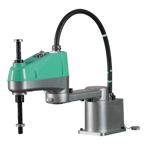 The kinematics plays a key role in SCARA robot’s movements. Image courtesy of Mech. Design.
What is Kinematics?
The branch of mechanics that is concerned with the description of motion is called kinematics. Kinematics differs from dynamics. Dynamics considers the forces and torque applied on an object that causes motion. The focus of kinematics is primarily on how objects move through space over time. Such elements associated with kinematics include speed, direction, and location of an object at a given point in time.
When kinematics is applied to maker projects, the analysis plays an important role in designing machines and mechanisms that move. The analysis allows the speed, direction, and location to be determined, which affects the target object's mechanical mechanism performance. The performance of a 3D printer’s nozzle precise printing path or a robot arms’ movement can be predicted using kinematics. The outcome of the kinematic analysis can be included in the design of the mechanical mechanism.
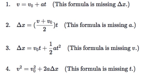 Kinematic Equations for Motion. Image courtesy of kmbphysics.
Position and Displacement
Position refers to where an object is in space. When working with a robot arm or a CNC machine, the position of the tool or end-effector (the part that interacts with objects) needs to be always known to control the system effectively. Displacement refers to the change in position of an object. If a robotic arm moves from one point to another, the displacement is the distance and direction between the two points. This displacement element is important for ensuring that the machine moves to the correct distance to perform tasks like picking up objects, cutting materials, or printing components.
 Translation of an end effector to a point in 3D space model.
Velocity
Velocity describes how fast an object is moving in a particular direction. For makers, controlling velocity is critical in machines like 3D printers, where the nozzle must move at the right speed to ensure smooth layers, or in robots that must navigate smoothly through space. Unlike speed, which only considers how fast something is moving, velocity assesses the direction of movement. Understanding velocity ensures that projects can move not only at the right speed but also in the right direction, which is essential for tasks like controlling a drone’s flight or making sure a CNC machine carves a material correctly.
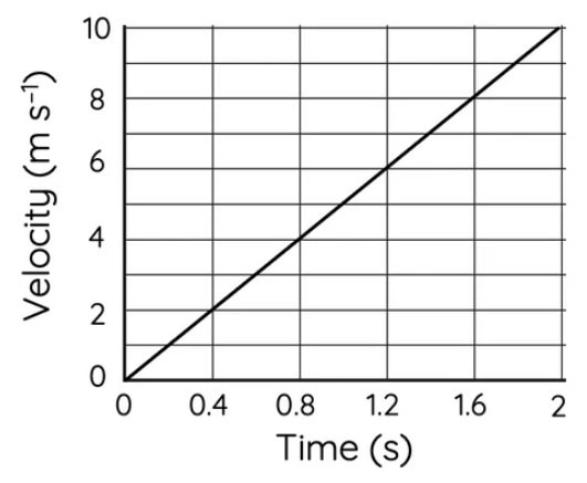 The mechanics of velocity. Image courtesy of Scienceready.com
Acceleration
Acceleration is the rate at which velocity changes. This means how fast an object speeds up, slows down, or changes direction. When building a project like an autonomous vehicle or robotic arm, controlling acceleration is essential for smooth and accurate movements. For example, a robot’s movement should not jerk when it starts moving, the use of controlled acceleration ensures gradual starts and stops, which is especially important in precision applications. By controlling acceleration, wear and tear on a machine’s motors and mechanical joints can be reduced by preventing mistakes like overshooting or undercutting in CNC processes.
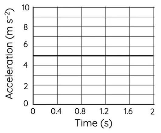 The mechanics of acceleration. Image courtesy of Scienceready.com
Forward and Inverse Kinematics in Robotics
Forward and inverse kinematics play an important role in robotics. The impact of these elements is the movement control of the robotic arm or manipulator that uses multiple joints or degrees of freedom (DOF) can be effectively controlled. Forward and inverse kinematics can be modeled using trigonometric equations and matrices. Software packages like Matlab or the Python programming language can be used to model and analyze forward and inverse kinematics of robotic arms. This section will briefly explain the analysis features of forward and inverse robotic kinematics.
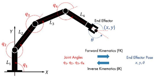 Forward and inverse kinematics of robot arm. Image courtesy of Mathworks.
Forward Kinematics
Forward kinematics involves determining the position and orientation of a robot’s end-effector based on the known positions or angles of its joints. For example, knowing the specific angle of each joint in a robotic arm, forward kinematics allows calculating the exact position of the arm’s end-effector (such as a gripper or tool). This is useful in applications like guiding a robot to follow a specific path or perform a task in a known space. In a pick-and-place robot, the position of the gripper needs to be known so it can correctly pick up objects from a conveyor belt. Using forward kinematics will ensure that the gripper moves to the correct location based on the robot’s joint configurations.
Inverse Kinematics
The opposite of forward kinematics is inverse kinematics. Inverse kinematics is focused on determining the angles or positions of the robot’s joints that will result in the end-effector reaching a specific point in space. This is often a more complex process because multiple joint configurations can achieve the same end position, or in some cases, no solution may exist. Therefore, a thorough understanding of the robot’s mechanical design will allow an appropriate setup of inverse kinematics equations and analysis to occur. When building a robotic arm, the task of picking up an object at a specific location, the joint angles of the machine will need to be solved to move the gripper to that position. This is critical for precision tasks, where accuracy is vital, such as assembling parts on a production line or performing intricate tasks like soldering components.
Linear and Rotational Kinematics
In kinematics, motion can be either linear or rotational. These two types of motion are often used together in mechanical and robotic systems, such as in drones, cars, or robotic arms. Another term used to describe the combined linear or rotational movement is known as rolling. Rolling is a common movement seen in machines like automobiles or bicycles.
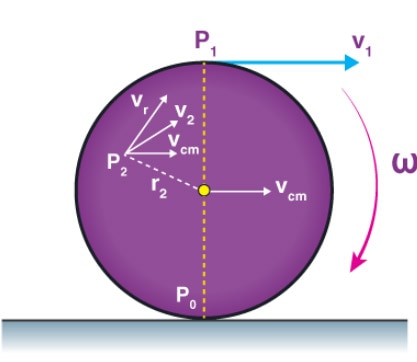 The basic kinematics of object rolling. Image courtesy of BYJUS.
Linear Kinematics
Linear kinematics deals with motion along a straight path. This is common in applications like conveyor belts, sliding mechanisms, or the movement of a 3D printer’s extruder head. In these systems, it's essential to understand how far and how fast something is moving along a particular axis. A 3D printer’s nozzle that moves linearly across the x, y, and z axes to create an object is an example of linear kinematics.
Rotational Kinematics
Rotational kinematics deals with objects that spin or rotate around an axis. This type of motion is common in systems like motors, gears, wheels, and even robotic joints. In rotational kinematics, you're concerned with the angle through which an object rotates, how fast it rotates, and how quickly it accelerates or decelerates. In a drone, controlling the rotational movement of the propellers ensures stable flight. Similarly, in a robotic arm, the joints typically rotate to move the end-effector, and understanding the rotational kinematics is key to making sure the arm moves smoothly and accurately. Both linear and rotational kinematics are essential in robotics, where joints often rotate to move parts along straight paths, such as in the case of a robotic arm that rotates its joints to move the gripper in a straight line.
 Pure Rotation Model of an End Effector around the x-axis. Image courtesy of the author.
Practical Applications of Kinematics for Makers
Now that the basic principles of kinematics have been explained, let’s look at how these concepts can be applied in real-world projects. Whether you’re working on 3D printers, CNC machines, or robots, kinematics plays a critical role in ensuring that your creations function correctly and precisely.
3D Printers and CNC Machines
In 3D printers, controlling the movement of the print head is essential for creating accurate and high-quality parts. By applying kinematics, you can ensure that the nozzle moves at the correct speed and follows the desired path across the x, y, and z axes. CNC machines rely on precise movements to cut or engrave materials. Kinematics helps you control the velocity, position, and acceleration of the cutting tool, ensuring that it follows the programmed path accurately and avoids overshooting or damaging the material.
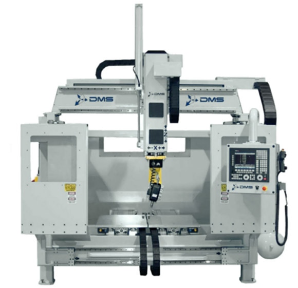 A typical CNC Machine. Image courtesy of DMS
Robotic Arms
Robotic arms are a common maker project, whether they're designed for tasks like pick-and-place operations, 3D printing, or light assembly. Kinematics helps you control the arm’s joints and end-effector, ensuring that it moves smoothly and reaches the correct positions. By applying forward and inverse kinematics, the control of a robot to pick up objects from specific locations and place them accurately on a workbench can be accomplished. Forward and inverse kinematics become especially important when working with multi-axis robotic arms, which have multiple joints that need to work together to move the end-effector precisely.
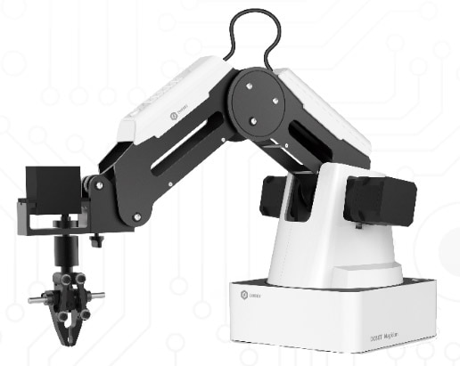 A typical robotic arm. Image courtesy RobotLAB.
Animatronics and Articulated Models
Kinematics is also useful in animatronics and projects that involve lifelike movements. When building a robotic hand or an articulated model, understanding how to control the movement of individual parts allows smooth and realistic motions to be created. In an animatronic project, the need to control the movement of joints in a character’s arm or leg is required. By understanding the principles of kinematics, the movements will look natural and coordinated, thereby creating a more lifelike effect.
 Animatronics impacted by kinematics. Image courtesy of poormansguidetoanimatronics.
Conclusion
Kinematics is an essential concept for the maker community, offering the tools and knowledge to design and control motion in your projects. Whether working with 3D printers, CNC machines, robotic arms, or animatronics, understanding how things move allows more precise, functional, and creative designs to be produced. By mastering the basics of position, velocity, acceleration, and applying concepts like forward and inverse kinematics, your projects can go to the next level. Kinematics offers a framework for predicting and controlling motion, enabling creations to come to life with accuracy and precision.
Have questions or comments? Continue the conversation on TechForum, DigiKey's online community and technical resource.


