How to Get Started with Bottango
2024-08-19 | By Maker.io Staff
Working with robots and animatronics with numerous actuators can seem daunting. Making them mimic fluid and lifelike motions precisely requires hundreds of lines of code and numerous hours of testing. Thus, this article explores Bottango, a program that proves that this process can be fun and intuitive and doesn’t have to be tedious or complicated.
What is Bottango?
Bottango is a software package that contains an Arduino-compatible driver and an animation program for personal computers. More advanced developers can also utilize any other microcontroller by implementing the Bottango API. Together, the driver and the animation programs help create elaborate movement patterns for various animatronics and other robots. The driver board receives commands from the computer program acting as the server via USB. Bottango users can create custom robots by telling the Bottango server about the controllable motors and servos. By doing so, you can orchestrate the movements of diverse robotic devices, such as robotic arms and bipedal walkers.
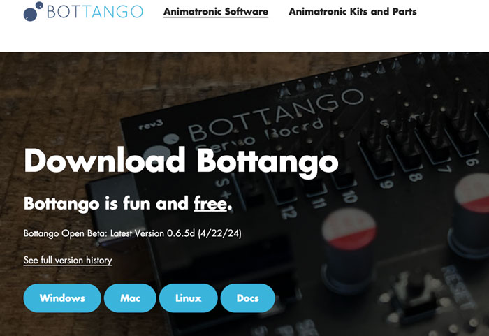 The Bottango Server program can be downloaded for all major computer operating systems from the official website.
The Bottango Workflow
The Bottango workflow consists of six basic steps. Start by either loading a predefined robot model or creating a custom definition that matches their hardware. During this step, you will create a visual representation of the hardware within Bottango and define movable parts and joints. Next, tell Bottango about the robot's controllable motors and servos. This step entails adding details, such as the Arduino PINs used for controlling the motors, their locations on the robot, and movement angles. Then, upload the hardware driver firmware to the Arduino or another compatible development board. The fifth step is optional, and it allows adding audio clips to the robot to synchronize the audio playback to the animation. In the final step, use Bottango's WYSIWYG (what-you-see-is-what-you-get) animation editor to define elaborate movement patterns without having to write a single line of code.
Creating a Visual Representation in Bottango
Start by importing a 3D model of your robot into Bottango or creating one from scratch. Bottango offers basic 3D primitives and modeling tools for that purpose. After accepting the Bottango terms of service, you are greeted by the start screen. Here, you can either begin with one of Bottango’s pre-defined designs or create a new one by clicking the highlighted option:
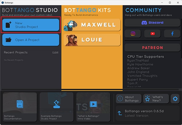 Selecting the highlighted option creates a new, empty Bottango project
The modeling process starts with adding parts once the empty project opens up:
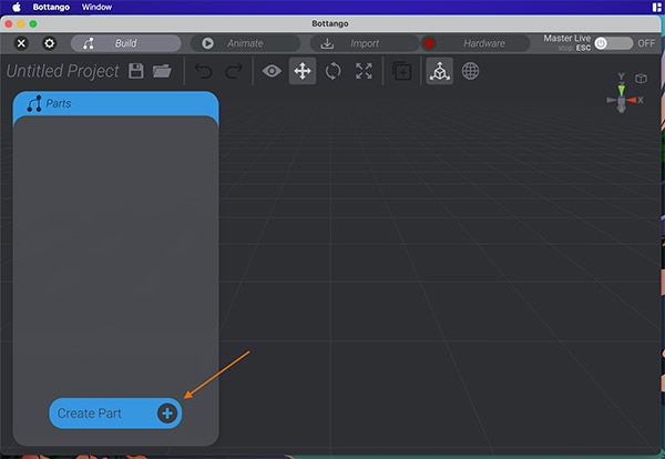 Use the highlighted button to create a new part in Bottango
Clicking the highlighted button opens a new pop-up panel that lets you select what you want to add. During this first step, add any of the highlighted 3D primitives to start creating a virtual 3D model of the robot:
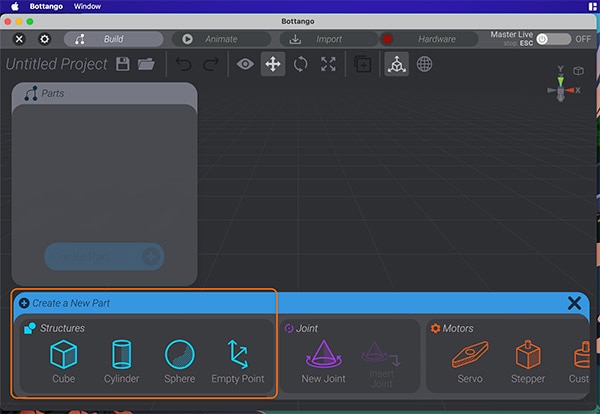 Use the available 3D primitives to create a 3D model of the robot in Bottango.
After adding a 3D part, users should name the components appropriately to make identifying them in the parts list easier. Doing so becomes especially important when working on more complex robots. After giving the component a name, employ the marked buttons to move, rotate, and scale the selected part. You can either use the handles in the center of the primitive or manually enter values in the text boxes at the right-hand side of the screen:
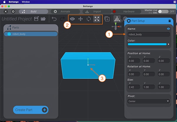 Follow these steps to add, name, and manipulate 3D primitives in Bottango.
The goal of this step is not to build an exact depiction of the robot in Bottango. Instead, the focus is on accurately recreating the parent-child relationships between the robot's parts. Take, for example, the following simple bipedal walker:
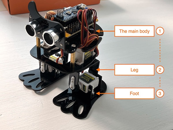 This image illustrates the parent-child relationships between the individual parts of a robot.
Each foot is attached to one leg, and each leg is connected to the body. The main body is at the highest level. It is the parent to all other components. If a parent moves or rotates, so do all its children. Thus, the body is the primary parent, and each leg is the parent of one foot. These relationships need to translate to the 3D model in Bottango by assigning the parts the correct nesting level:
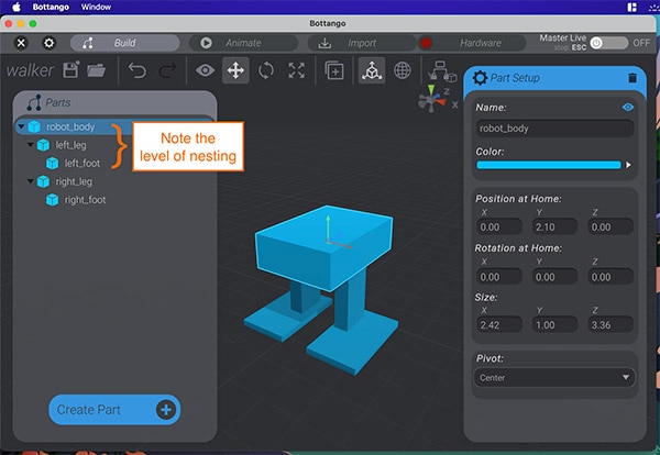 Ensure the correct parent-child relationships of the created 3D model’s individual parts.
It’s worth mentioning that you should model the robot in its neutral (or resting) position. Once you have created the 3D model, you can move on to the next step of the Bottango workflow, which is adding virtual joints.
Adding Joints to a 3D Model in Bottango
Virtual joints model the allowed movement between the static parts of a 3D model in Bottango. The joints are the structures that rotate or move along a single axis, serving as the pivot points for the model's movement.
To begin, click the CREATE PART button (from before) again. However, this time, add a joint instead of a 3D part. Then, each joint must be placed in the 3D position where a movement should occur. For example, each of the two leg joints must be placed on the 3D model where the leg meets the body:
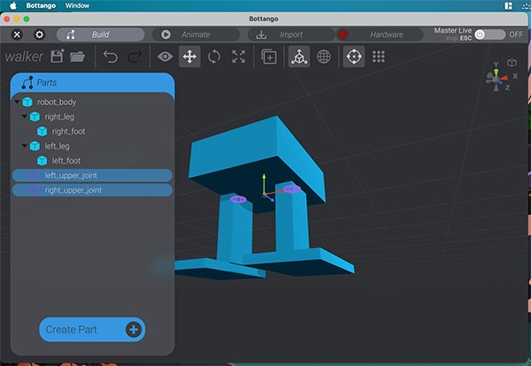 Place the joints in the 3D space where you want to allow movement to happen.
Bottango will likely add the joint at the bottom of the parts list. However, a part that a joint can manipulate must be a child of that joint in Bottango. Like before, manipulating a parent object also affects all attached children, so joints must be positioned on the 3D model before assigning the child objects. Once done, drag-and-drop the joints to the correct nesting level in the hierarchy, just like you did before with the 3D primitives:
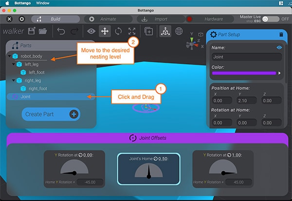 Follow these steps to make all necessary 3D objects children of the appropriate joint.
Joints can also be rotated to allow movement or rotation along different axes. Alternatively, you can also use the dropdown in the joint options along the right-side edge of the editor window to change the axis. In this example, the joints at the robot’s feet need to be rotated along the x-axis by 270 degrees:
 Rotating the joints allows for manipulations along different axes.
Once that’s done, you can preview the joint movement to ensure that the model’s parts act as intended by using the following button after selecting a joint:
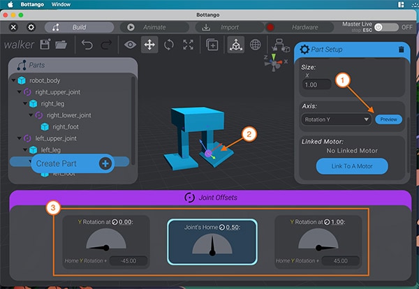
Use the highlighted button to test the joint. Then, verify that it moves correctly. Use the outlined buttons to adjust the settings if necessary.
It’s worth reviewing all the joints and verifying that all attached components move as expected. If necessary, you can use the joint offset adjustments to correct the behavior until the joint moves as expected.
Controlling Bottango Joints with Motors
Joints alone only represent movable parts, but they do not move components. For that purpose, you must place motors in the design and link the joints to the motors. Currently, Bottango supports servos and stepper motors. These virtual motors allow setting the minimum and maximum PWM values of servos, for example, to ensure that the values sent to the Arduino board make the real-life motors behave correctly. Further, this is where you define the GPIO pin used to control a motor.
To add new motors, use the same menu as before. Each motor should be given an appropriate name before adjusting the motor pin and settings as needed:
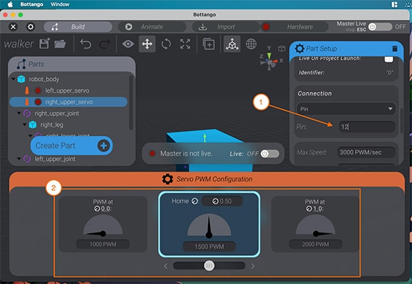 Add motors and adjust settings as needed.
Next, select a joint from the parts list and link it to the motor in the design that should move the joint:
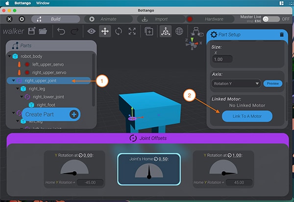 Select the joint in the parts list and link it to a motor.
Bottango then confirms that the joint and motor are linked:
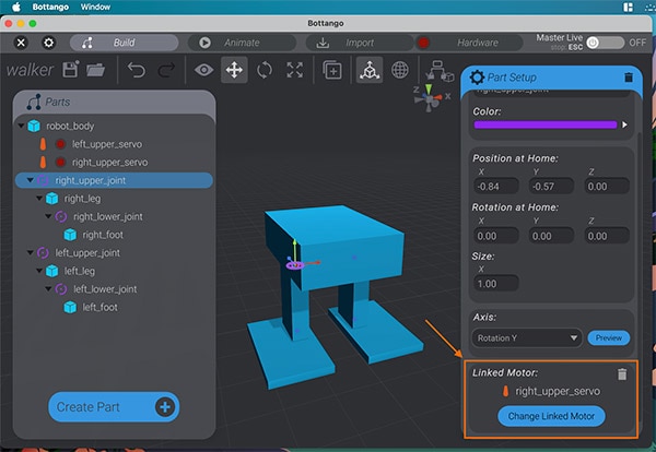 The highlighted box shows that linking the joint and motor worked.
Repeat these steps for all motors and joints in the design before proceeding.
Uploading the Bottango Hardware Driver Firmware
Before creating animations, upload the Bottango driver firmware to your hardware controller. Bottango supports many Arduino boards, and the program includes the custom drivers needed for controlling the robot’s motors. You can upload the firmware using the Arduino IDE. In the IDE, they have to navigate to the folder where they installed Bottango and load the driver project:
 Use the Arduino IDE to upload the BottangoArduinoDriver.ino file to an Arduino
Once done, reset the Arduino board, close the IDE, and toggle the MASTER-ON button in the top-right corner of Bottango. The Bottango server should automatically detect the driver board. If it does not, you can click on the HARDWARE button left of the toggle switch and then adjust the settings in the DRIVERS tab as needed. Adjusting the port will likely solve most connectivity problems. At the end of the process, the small green indicator next to the HARDWARE button should light up green.
 Follow the outlined steps to activate the driver and select a port.
The left indicator shows the driver board status and the right one displays inactive motors. To resolve the problem, select the status tab and then toggle on all devices. The red indicator should disappear, leaving only a single green one visible:
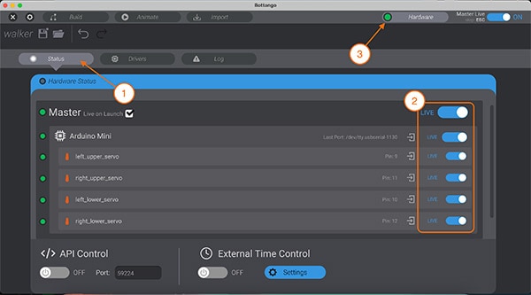 After following the steps, the hardware button should only show a single green indicator.
Creating a Basic Animation Track in Bottango
After completing these steps, you can start animating the robot using Bottango. Animate joints by adding an animation track for each joint you want to manipulate. To get started, switch to the ANIMATE tab and then click the ADD TRACK button:
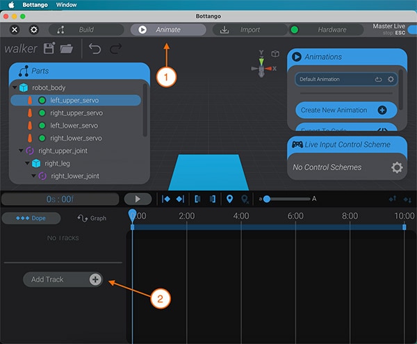 The highlighted steps create a new animation track in Bottango.
Doing so opens a pop-up window where you must select the type of track, which is “Joint Track” in this instance:
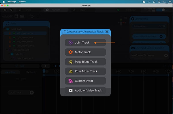 The marked option adds a new joint track.
The program then requires you to choose one of the previously created joints. You must select and manipulate a joint in the 3D view to animate it. The timeline scrubber indicates the time since the animation started. By moving the scrubber and adjusting the joint rotation or position, you can instruct Bottango to create a new keyframe that stores the updated joint transformation. By repeating this multiple times, you can define how a joint’s position or rotation changes over time. Bottango takes care of the math involved in the process, and it interpolates missing angles between keyframes:
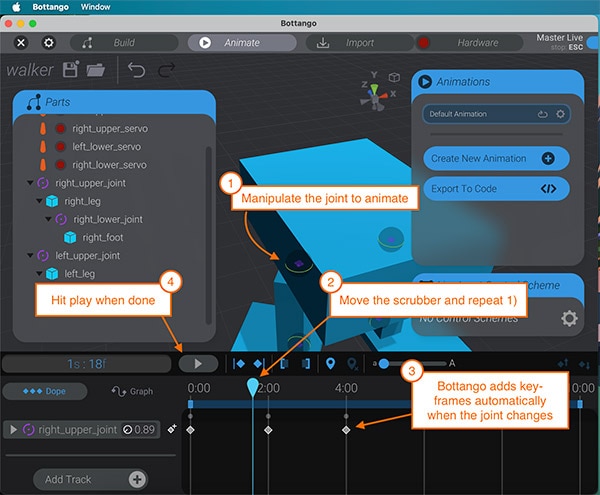 This image illustrates the basic steps of creating an animation in Bottango.
During this process, makers must ensure that the robot is not obstructed because Bottango directly previews the 3D movements using the real hardware as long as the driver and motors are all enabled.
Summary
Bottango is a two-part program for creating elaborate robot movement patterns without requiring users to write a single line of code. Instead, Bottango users follow a six-step workflow in which they recreate the robot in 3D space, define the moving parts, and add virtual motors that represent the actual hardware.
After uploading the included firmware to a compatible development board, toggle on the hardware driver in Bottango, select the correct serial port, and toggle on all of the robot's motors.
Once the robot is set up, users can bring it to life with Bottango's powerful built-in animation tool. They can easily translate virtual joint manipulations to real-world movements by advancing the timeline scrubber to the desired position, adjusting the joint's rotation or position in the 3D editor, and letting Bottango handle the rest. It translates the change to the necessary PWM adjustments, interpolates missing positions between keyframes, and allows you to preview the animation with a single click of the PLAY button.

Have questions or comments? Continue the conversation on TechForum, DigiKey's online community and technical resource.
Visit TechForum


 中国
中国