制造商零件编号 CFR-25JB-52-47K
RES 47K OHM 5% 1/4W AXIAL
YAGEO
Recently, we had the privilege of attending Open Sauce in San Francisco. It was an exceptional event, with a variety of prodigious projects, exciting exhibits, tremendous talks, and commendable creators. Badges for this year’s event were PCBs sporting the Open Sauce logo, complete with traces and footprints to add blinking eyes to the robot's face.
If you were lucky enough to attend the event or have found yourself in possession of one of these coveted badges and are looking to build out the circuit, we are here to help. You can find the full parts list and build instructions below. Whether this is your first-time soldering, or you are a seasoned pro, this guide will help you expand your skillset with pro tips along the way.

Interested in learning how the badge works? You can learn more about it in our Design and Build a Simple Analog LED Flasher Circuit tutorial!
Step one is to acquire all the parts needed to assemble the badge, luckily all the components needed are through-hole, meaning the leads of the component poke through the PCB for easy soldering of the leads on the reverse side of the board. Below you will find a list of the needed resistors, capacitors, and transistors and a link to find compatible LEDs. The pin spacing for the badge LEDs is designed to accommodate 5mm LEDs, a common size LED often referred to as T-1 3/4; however, you may be able to use other LEDs if the lead spacing is similar.
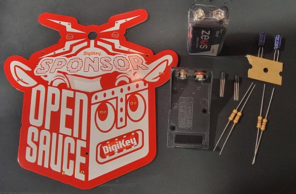
1- 9V Battery
Select your 5mm through-hole LEDs here: https://www.digikey.com/short/w773p2wc
For my badge, I chose to use UV purple LEDs, which, if you also would like to use UV LEDs, you can find compatible options here: https://www.digikey.com/short/v2bqpc85
Finally, if you really want to get creative with your badge, we have some compatible novelty LEDs that may be of interest to you here: https://www.digikey.com/short/wd83z5dq
When populating a PCB, you generally want to start with the shortest components and add taller components as you go to make it easier to ensure that all components are mounted tight to the board.
All the components for this badge will be mounted on the front side, where we find the Open Sauce logo and robot, except for the battery holder.
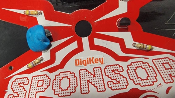
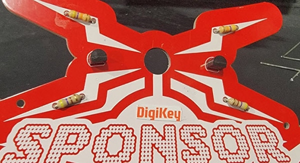
Resistors are not polarized, so it doesn’t matter which lead you insert into each hole. However, since this badge is more of a visual element than your typical PCB, I suggest you mount all resistors in a similar orientation for aesthetics. You can see in the image below that I placed all resistors with the gold tolerance band towards the center of the badge.

Through-hole resistors are labeled with colored bands. You can double-check the value of your resistors using the DigiKey Resistor Color Code Calculator. Ensure you place the 47KΩ resistors in the top spots, and the 470Ω resistors in the correct spots below. If you accidentally swap these, your badge will not work.
Bend the leads of the resistors to a 90-degree angle as close to the resistor body as possible and insert the leads through the respective holes in the PCB until the resistor is flat against the surface of the badge. Then, to hold the resistor in place while soldering, splay the resistor leads to prevent it from falling out when you flip the board.
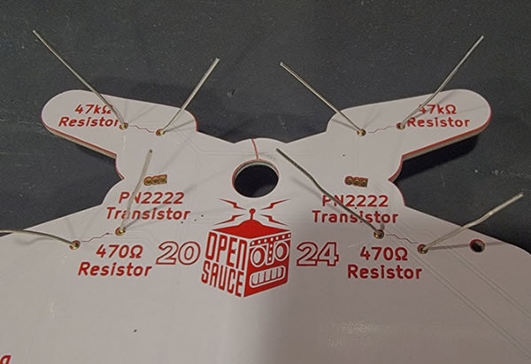
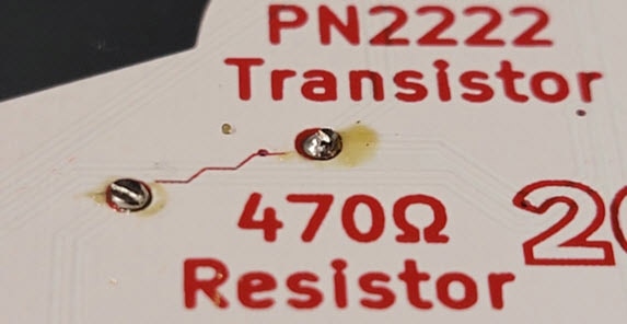
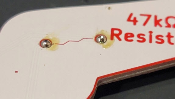
Once all 4 resistors are fully inserted into the board and tightly held in place, flip the badge, and solder the leads on the back side, then trim off the excess wire lead.

First time soldering? Learn How to Solder with Becky Stern
Pro Tip: Use tape or mounting putty to help hold the component in place while soldering.
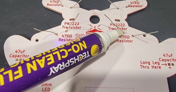
Pro Tip: Adding extra flux when soldering makes the task quicker and easier. Use a flux pen or paste flux for better solder joints.
Pro Tip: Clipped leads can leave sharp points on your PCB. For wearables and badges, for comfort and to avoid snagging clothes, trim the excess lead with a flush cutter as close to the PCB as possible, then briefly reheat the solder joint, resulting in a smooth bump of solder, free of any sharp points.

Insert the transistors into the PCB ensuring they match the outline on the front of the badge to ensure correct polarity.
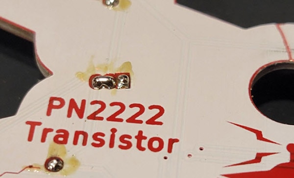
With both transistors held firmly in place, flip the badge, and carefully solder the leads as you did with the resistors. Since the solder pads for the transistors are quite small and close together, after soldering you should trim the leads and carefully inspect the solder joints to ensure that none of the pads are shorted together. If they are shorted, use some solder wick to remove the excess solder.
Curious about what a transistor is and how it works? Discover Transistor Basics: NPN & PNP Using 2N3904, 2N3906, 2N2222, and 2N2907
Pro Tip: Add a bit of flux to your solder wick before attempting to remove excess solder from your PCB to wick up the extra solder quickly.
Before installing the capacitors on the front side of the badge, take note of the longer, positive lead and ensure the capacitor is installed in the correct orientation. If you install the capacitor with reverse polarity, it may damage the component, and possibly cause it to violently rupture. You may choose to install the caps standing upright; however, I chose to bend the leads to lay them flat against the badge to help prevent them from getting caught on clothes or lanyards.
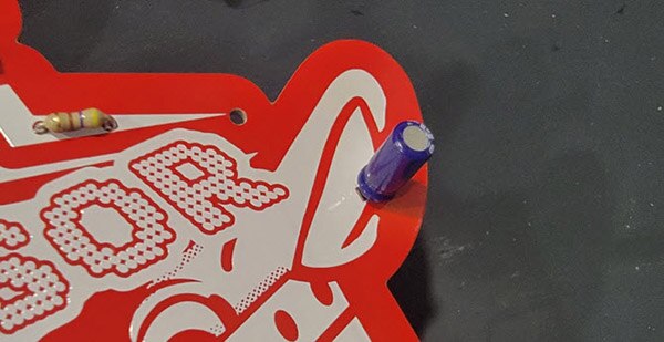

With the capacitors secured in place in your desired position, you can now solder these components in place and trim the excess leads.
Pro Tip: Polarized components with only two leads often have a longer positive lead. One method of helping to remember this orientation is if you cut the excess off the longer lead, and lay it across the remaining lead you cut it from, it would make a plus sign +
Insert your chosen LEDs through their respective holes in the front of the board, taking note of proper polarity. With the LEDs fully seated against the PCB, bend the legs on the back side, flip the badge, and solder and trim these leads as before.


What is an LED? Explore LED Basics with Becky Stern
Install the battery holder on the back of the badge in the designated holes, then flip the badge to solder and trim the leads.

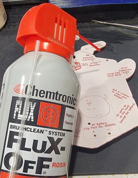
Pro Tip: With all components soldered into place, use some flux remover to clean up the board. This not only improves the appearance; it also removes any leftover sticky residue and prevents any remaining flux from corroding the PCB.
If you find that your battery holder is not well supported once the battery is installed, add a bit of hot glue between the holder and the PCB to prevent it from moving.

Pro Tip: If you need to remove hot glue, first wet it with isopropyl alcohol. This will release the surface bond between the glue and the substrate, allowing you to easily peel the glue away.
With the battery now installed, you should see your LEDs alternately blinking, as shown below. If not, check that components are installed with the correct orientation, verify there are no shorts, and inspect your solder joints for any bad connections.
