Programming a RoundyFi LCD to Display Messages
2023-03-13 | By Don Wilcher
Displays LCD / TFT Arduino ESP8266
Traditionally, Liquid Crystal Display (LCD) optoelectronic components are packaged in a square or rectangular shape. The LCDs use individual pixilated squares, allowing letters or graphic characters to be created, and they might have their own embedded microcontroller to drive the pixels etched into the thin layer of glass. Although square LCDs are prominent visual units for electronic projects, a unique form of the LCD to display text and graphics is available for makers, hobbyists, and professionals to experiment with.
The RoundyFi is a round LCD capable of displaying text and graphics. This hands-on tutorial will teach you how to set up, program, and use the RoundyFi LCD module to display text for messaging and interactive devices!
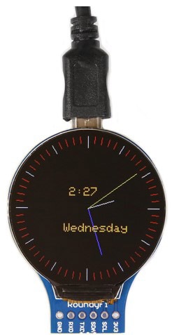 The RoundyFi LCD module.
The RoundyFi’s Specifications
Here are some key specs to know about what we’re working with today: the RoundyFi is an optoelectronic module that uses an Espressif ESP8266 microcontroller. The ESP8266 has an 80 – 160 MHz operating frequency range and WiFi capabilities supporting the IEEE 802.11/b/g/n wireless specification. The ESP-12E has an operating supply voltage of 3.3V. The four General-Purpose Input-Output (GPIO) pins accessible at the bottom of the RoundyFi are 3.3V compliant, and a USB MicroB connector port is located at the top of the RoundyFi. A CP2101 IC supports the serial communication USB to UART interface. This serial communication circuit interfaces the USB port to the ESP8266 microcontroller. The CP2101 USB to UART interface provides easy programming and debugging software on the RoundyFi LCD module.
The RoundyFi packages a 1.28-inch LCD driven by a GC9A01 In-Plane Switching or IPS module. The RoundyFi uses various features to program and create aesthetically pleasing visuals and effects for maker projects. The RoundyFi LCD visual and programming capabilities are illustrated below.
 The RoundyFi LCD module’s features.
RoundyFi LCD Module Setup
The setup procedure of the RoundyFi LCD module is accomplished using the Arduino Integrated Development Environment (IDE). The first setup step is to download the Arduino IDE. You can download the Arduino IDE here.
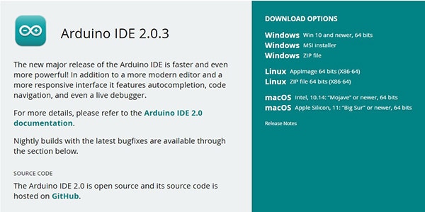 The Arduino’s latest IDE software version.
With the latest Arduino software version downloaded and installed, open the IDE. Note: The image below shows the IDE is displayed in Dark Mode. If Dark mode is desired, Go to File> Preferences >Theme and select Dark (Arduino).
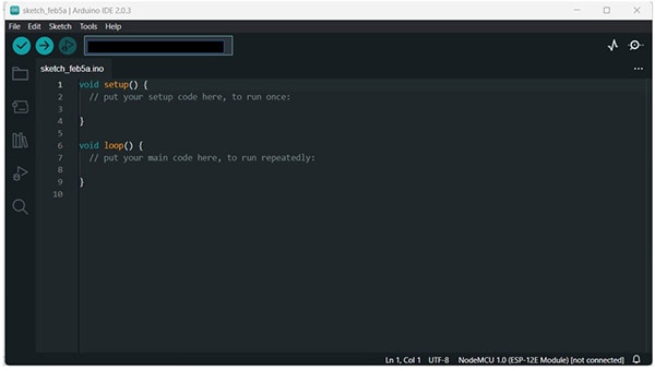 Arduino IDE opened.
Install the Esp8266 board by going to File>Preferences. Scroll down to Additional board manager URLs, and in the text box, paste the following two URLs.
http://arduino.esp8266.com/stable/package_esp8266com_index.json
https://dl.espressif.com/dl/package_esp32_index.json
 Adding two URL addresses to the board manager.
To install the ESP8266 boards within the Arduino IDE, access the Boards Manager as shown below. In the search box, type in ESP8266. The latest version of the ESP8266 board manager at the time of writing to install is 3.0.2.
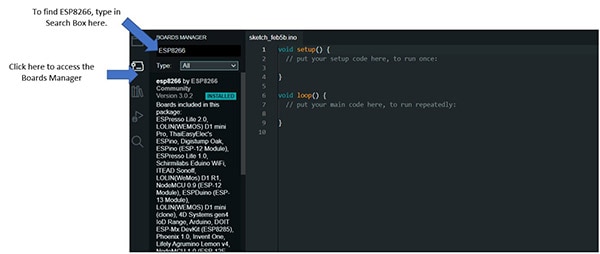 Installing the ESP8266 board manager’s software.
The next step in the ESP8266 board software process is to check the installation of the boards. For this, go to tools>boards, then check for the ESP8266 installed boards. The ESP8266 boards’ installation is shown next.
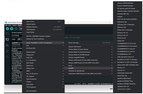 ESP8266 boards installed within the Arduino IDE.
The final step of the software process is the installation of the GFX Library for Arduino. To access the Arduino library, type GFX Library for Arduino in the search box. Once the library is visible, install version 1.3.1.
The ESP8266 boards support the Espressif family of microcontroller development and board kits. The version of the board you’ll use in this tutorial is the NodeMCU 1.0 ESP-12E module. The GFX library will have the support of the GC9A01 IPS module responsible for managing the text, colors, and graphics of the RoundyFi LCD unit. We can now wire a small demonstration circuit using a few off-the-shelf electronic components.
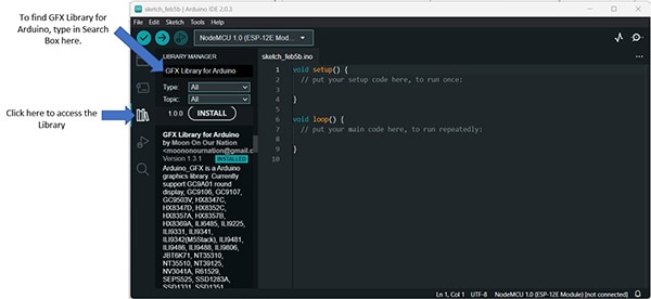 GFX Library for Arduino software installation.
Wiring of The RoundyFi LCD Demonstrator Circuit
We’re ready to start wiring a basic RoundyFi LCD Demonstrator circuit. The demonstrator circuit will allow several important software and electrical items to be tested, such as the following:
- USB communication between the RoundyFi LCD module and a PC.
- Proper installation of the ESP8266 NodeMCU 1.0 ESP-12E module software and the GFX Library for Arduino package.
- Proper wiring and operation of the tactile pushbutton switch with a pulldown resistor (10KΩ value).
The parts list and an electronic circuit schematic diagram can be found on Scheme-It. Check that out here!
Upon receiving your RoundyFi LCD module, solder the 6-pin male header to the PCB. After soldering the header pins to the PCB, you will use the electrical wiring diagram shown in Figure 9 to wire the RoundyFi LCD Demonstrator circuit on a solderless breadboard. Figure 10 shows the equivalent electronic circuit schematic diagram of the RoundyFi demonstrator device. The operation of the demonstrator is to provide a 3.3V control signal to the Serial Clock Line (SCL) pin on the RoundyFi LCD printed circuit board (PCB). The duality of the ESP-12E module is that the SCL can act as a GPIO pin. The SCL is GPIO5 of the ESP-12E microcontroller module.
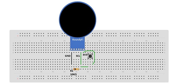 The RoundyFi LCD Demonstrator electrical wiring diagram.
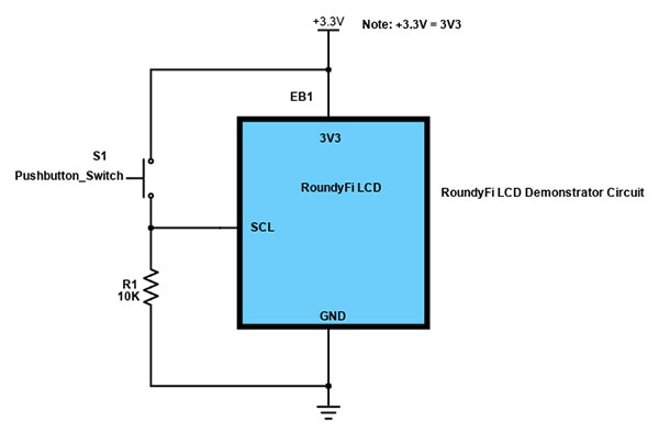 The RoundyFi LCD Demonstrator electronic circuit schematic diagram.
Here is the wired RoundyFi LCD Demonstrator circuit. The final step in this tutorial is uploading the Hello World C++ code (the Arduino sketch) to the demonstrator.
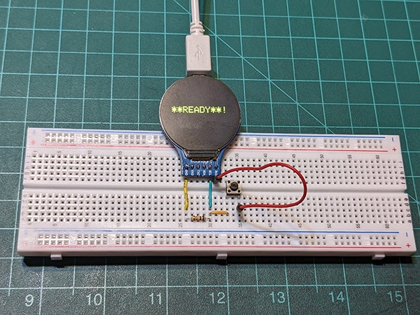 The completed RoundyFi LCD Demonstrator circuit.
Upload Hello World Code to the RoundyFi LCD Demonstrator
You will upload the Hello World code to NodeMCU 1.0 ESP-12E module to test the demonstrator circuit. Attach the RoundyFi LCD module to your desktop PC or laptop computer’s USB port. Select the NodeMCU 1.0 ESP-12E using the discussion information on viewing the ESP8266 installed boards. Select the appropriate USB or communication (COM) port from the dropdown list. Next, the correct board and COM port selected within the Arduino IDE is illustrated.
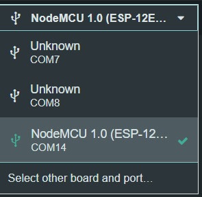 NodeMCU 1.0 ESP-12E board and COM port selected.
Copy and paste the Hello World code within the Arduino IDE.
/* Pressing pushbutton switch wired to SCL (GPIO pin 5) will allow blinking Hello World to be displayed on
   a RoundyFi LCD

   by Dr. Don Wilcher 1/28/2023

  */


/* Back End GFX resources for initializing the RoundyFi LCD*/


#include <Arduino_GFX_Library.h>


#define GFX_BL DF_GFX_BL /*default backlight pin, you may replace DF_GFX_BL to actual backlight pin*/


#if defined(DISPLAY_DEV_KIT)
Arduino_GFX *gfx = create_default_Arduino_GFX();
#else /* !defined(DISPLAY_DEV_KIT) */
Arduino_DataBus *bus = new Arduino_ESP8266SPI(2 /* DC */, 15 /* CS */);
Arduino_GFX *gfx = new Arduino_GC9A01(bus, 16 /* RST */, 0 /* rotation */, true /* IPS */);


#endif /* !defined(DISPLAY_DEV_KIT) */
/*******************************************************************************
 * End of Arduino_GFX setting
 ******************************************************************************/


/* Defining and initializing input variables*/


 const int PB_Switch  = 5;
 int PB_Switch_status = 0;
 int count = 0;


/* Setup of LCD attributes and input device*/


void setup(void)
{
    gfx->begin();
    gfx->fillScreen(BLACK);
    pinMode(PB_Switch, INPUT);


#ifdef TFT_BL
  pinMode(TFT_BL, OUTPUT);
  digitalWrite(TFT_BL, HIGH);
#endif

    gfx->setTextColor(YELLOW);
    gfx->setTextSize(3);

}


void loop(){


PB_Switch_status = digitalRead(PB_Switch); // reading Pushbutton Switch status
//count = count+ 1;


if (PB_Switch_status == HIGH) { // if Pushbutton Switch is pressed, blink Hello World Message on RoundyFi LCD

  gfx->fillScreen(BLACK);      // prevents combined messages from displaying on RoundyFi LCD
  gfx->setCursor(10, 100);
  gfx->println("Hello World!");
  delay(100);
  gfx->displayOff();
  delay(100);
  gfx->displayOn();


}
else {                           // if Pushbutton Switch is not pressed, display READY message on RoundyFi LCD


gfx->fillScreen(BLACK);          // prevents combined messages from displaying on RoundyFi LCD
gfx->setCursor(10, 100);
gfx->println(" **READY**!");
delay(2000);


}


}
Upload the code to the RoundyFi LCD module. After the code has been compiled and uploaded to the module, the “**READY**!” message will be displayed on the RoundyFi LCD. Pressing the pushbutton will display a blinking “Hello World!” on the LCD. The following pictures illustrate the operation of the RoundyFi LCD module and the Hello World! Code.
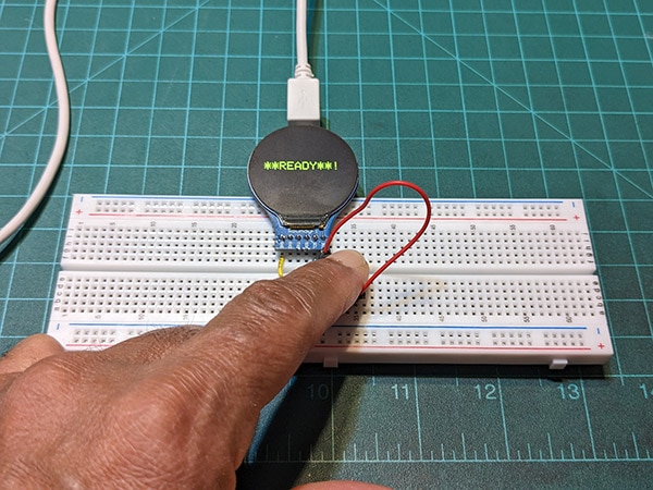 READY message displayed on the RoundyFi LCD.
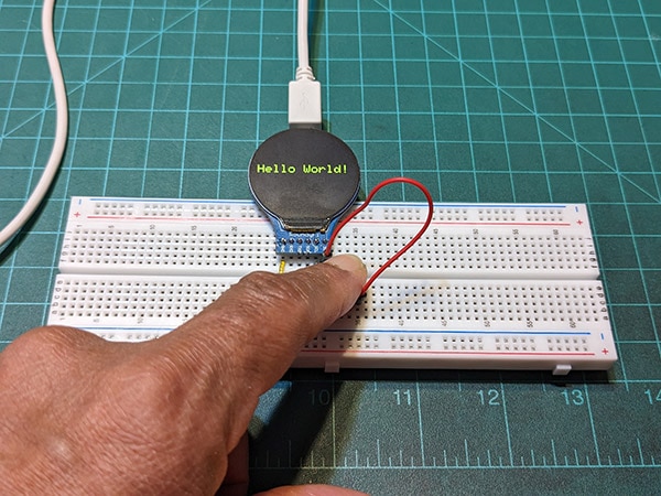 Blinking Hello World displayed on RoundyFi LCD.
As a reference, view the video clip of the RoundyFi LCD demonstrator circuit in operation here. As an additional activity, locate the gfx->println instructions and change the message to display your name or hobby. With the listed code commented, you can now explore and experiment with other visual effects of the RoundyFi LCD demonstrator using the Arduino GFX library.


