制造商零件编号 LTW-2S3D7
LED WHITE CLEAR T-1 3/4 T/H
Lite-On Inc.
Today we're building some simple circuits without the need for any code or programming. You’ll learn how to hook up some LEDs to a battery pack and also a simple circuit for playing audio.
To make a simple LED and battery circuit, you will need:

Here is a diagram of a basic LED circuit. As we covered in a previous video about LEDs, the positive side is connected to the battery's positive side and likewise negative to negative, with the resistor in series with the LED. The current will flow from the battery through the resistor and LED and then back to the battery. The resistor limits the current flowing in the whole circuit, regardless of whether it comes before or after the LED in the circuit– it’ll work either way. And resistors aren't polarized like LEDs, so their orientation doesn't matter.
Tin and solder the components according to the diagram, and don’t forget to add some heat shrink before the final connections. But if you’re new to soldering, you may want to hold off actually shrinking it until you’ve tested that it works first.
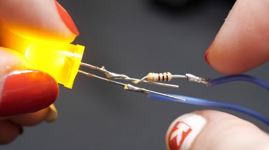
Install your batteries, verify their orientation, and flip on the switch. Your LED should turn on. If it doesn’t, double-check for a short circuit– two wires that are touching but shouldn’t. If you have a short, parts of your circuit may start to heat up. Remove the batteries right away if this happens, and correct the short before plugging them back in.
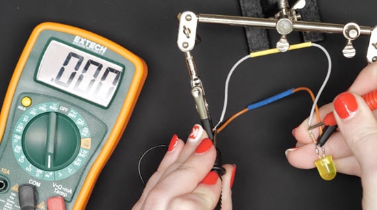
To test what’s connected and not, use a multimeter set to continuity mode. With the circuit off, touch the probes to either side of the connection in question, and if it beeps, it’s connected, and if it doesn’t, it’s not connected. You can check the whole circuit for things you know should be connected, and things you know shouldn’t be.

To add more LEDs to this setup, just wire them in parallel with the first one, meaning that each LED and resistor pair is connected to the battery at the same point. All the positives together, and all the negatives. This is the difference between series and parallel circuits. The resistor and LED are in series with one another, and the multiple LEDs are in parallel with each other.
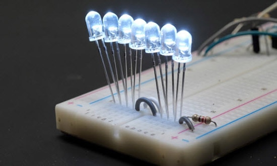
Beginners often ask if they can put just one resistor in series with multiple parallel LEDs. While this may work in a simulation, it’s not a good idea in practice and will cause one or more LEDs to eventually fail. This is because they aren’t all perfectly even conductors, so whichever LED has ever so slightly less internal resistance than its neighbors will start to attract more current, which over time can become more pronounced and even burn out the LED.
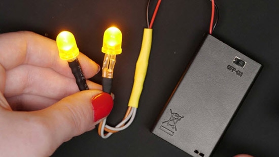
Try adding just two or three more LEDs before making any big plans to add a bazillion more. You can learn how to calculate the battery life in this DigiKey video by Shawn Hymel. It’s best to start out with LEDs of the same color and same value resistors. Once you start mixing and matching colors, which are electrically different from one another, the individual resistor values start to matter a lot more. Remember that electrical current takes the path of least resistance. You can use the DigiKey LED Series Resistor Calculator to select the proper resistor for each LED.
Making a sound circuit is also a great way to practice your soldering skills This easy-to-use audio fx board makes it possible. Here’s what you’ll need:
The board connects to your computer over USB and shows up as a flash drive. Load sound files onto it the way you would any other.

You must format the sound files according to the board’s specs, which can be easily done with the free audio editing program called Audacity.
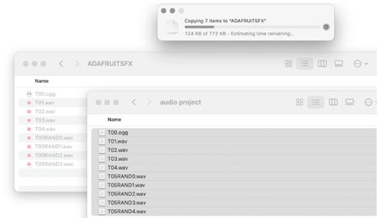
The way the files are named determines which trigger they are associated with, as well as the behavior, for example, I can make one trigger play randomly from a set of sounds by naming them accordingly.

To trigger the sound to play, one of the labeled connectors on the numbered of the board needs to be connected to ground, either permanently with a wire, or temporarily with a switch. You can plug in the audio fx board to a solderless breadboard, then wire switches from these trigger pins to ground. The speakers plug into the built-in amplifier. And that’s all there is to creating a simple audio circuit!

Once you’ve got it working on a solderless breadboard, you can transpose it over to a soldered breadboard to make it more permanent and embed it inside your next project.
Thanks for following along! Be sure to check out my projects on Maker.io.