How to Send and Receive Data Over IR Signals with an Arduino
2021-01-13 | By Maker.io Staff
Other Optoelectronics Light Infrared Receiver Arduino
A previous article explored IR transmission techniques in general and two popular transmission protocols. This article discusses how that knowledge can be applied to build Arduino-based devices and projects that can react to IR remotes. Furthermore, the Arduino can also be used to remotely control other devices, for example TVs, with the help of infrared signals.
Finding the Right IR LED and Receiver
BOM
Part/Qty.
- Perfboard - 1
- 38 kHz IR receiver - 1
- 39 Ohm resistor - 2
- IR LED - 1
- NPN transistor - 1
- CR2032 holder - 1
- CR2032 Lithium Battery - 1
- M/M Jumper Wires - 1
- Arduino Uno - 1
Note that this receiver uses a carrier frequency of 38 kHz, which is the same that the NEC protocol defines as its standard carrier frequency. As discussed in the previous article, slight deviations from that frequency shouldn’t pose a problem. Therefore, this device should also work with most RC5-based remotes, which use 36 kHz.
The same goes for the infrared LED, which emits light with a wavelength of 950 nm in this case. IR sensors typically are most sensitive to a certain wavelength. They’ll, however, still respond to IR LEDs that output other wavelengths within set limits (e.g. the near IR band). Keep in mind that different standards and schemes exist to categorize IR radiation, but most DIY and hobbyist projects should be fine when using off-the-shelf electronic components.
Building a universal IR receiver and sender module
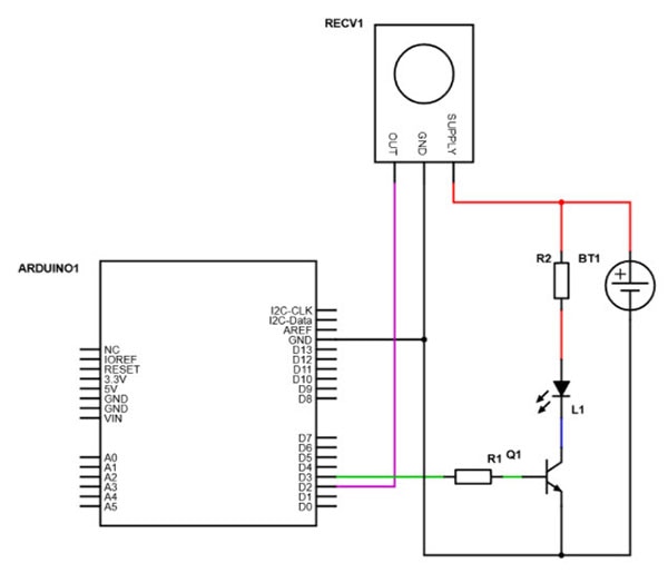
The following schematic shows a simple IR receiver and sender circuit that uses the parts from the part list above. This circuit will not only work with Arduinos, but it can also be employed in Raspberry Pi-based projects and other electronic devices.

View the full schematic here.
It’s possible to omit the battery and transistor and use the Arduino’s 3.3 V pin to power the circuit. That will, however, reduce the range of the transmitter.
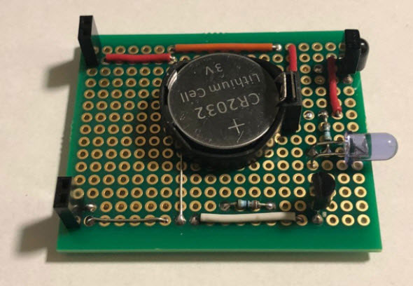
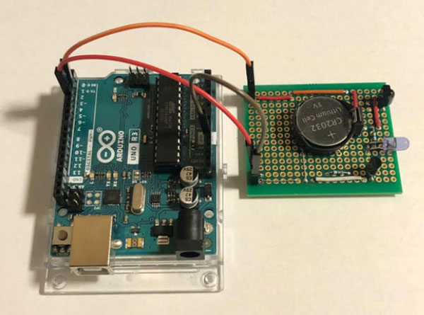
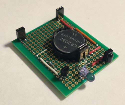
This design could also be taken a step further by adding a microcontroller to the board that handles the reading and parsing. The Arduino could then, for example, ask the microcontroller to transmit the parsed value via I2C instead of decoding the IR samples. The finished circuit for our article, however, looks like this:

Reading IR signals with an Arduino
Luckily, many libraries exist for the Arduino ecosystem that will diminish the main difficulties of working with IR receivers. These libraries usually implement the most popular communication protocols and take care of measuring the timings and converting the data to manageable hexadecimal values that are easy to understand and work with.
This article utilizes the popular open-source Arduino-IRemote library that can be downloaded from GitHub. A handy video that explains how to install such libraries can be found on the DigiKey YouTube channel.
Reading IR signals only requires a few library calls. The following sketch toggles the onboard LED of an Arduino UNO whenever the power button gets pressed on a particular NEC-compliant remote control:
/**
 * A simple test-sketch that uses the IRemote library to detect when the power on/off button
 * is pressed on an NEC remote control. If a button press is detected, the sketch toggles
 * the on-board state of the LED (pin 13 on the Arduino Uno).
 */

#include <IRremote.h>

#define IR_RECEIVE_PIN 2
#define LED_PIN 13

IRrecv receiver(IR_RECEIVE_PIN);

void setup()
{
  // There's no need to set up the IR_RECEIVE_PIN with pinMode
  // the library takes care of that...
  // pinMode(IR_RECEIVE_PIN, INPUT);

  pinMode(LED_PIN, OUTPUT);

  Serial.begin(9600);

  while(!Serial)
  {  }

  // Enable the IR receiver
  receiver.enableIRIn();

  Serial.print("IR Receiver ready!");
}

void loop()
{
  decode_results results;

  // decode returns 1 if something was received
  // otherwise it returns 0
  // The code and protocol type get stored in results
  if (receiver.decode(&results))
  {
	// The ON/OFF button was pressed on my remote
	// Note: The codes might vary across different remote controls!
	if(results.value == 0xFE50AF)
  	digitalWrite(LED_PIN, !digitalRead(LED_PIN));

	Serial.print(results.bits);
	Serial.print(": ");
	Serial.println(results.value, HEX);

	receiver.resume(); // Receive the next value
  }
}
The two define statements tell the script where the IR receiver output pin is attached and which LED to toggle. The setup function enables the serial monitor and the LED output pin. Note that there’s no need to set up the pin that connects the Arduino to the IR receiver. The library takes care of that step when a new IRrecv instance gets created.
The loop method uses the decode function of the IReceive library, which returns one when an IR signal is received. The result is stored for later use. If a signal was received, the script checks whether it corresponds to a certain hexadecimal value. Note that the values of your remote control might vary. Last but not least, resume() must be called to make the IRemote library wait for the next input.

Sending messages as IR signals with an Arduino
Luckily, sending IR signals is as simple as receiving them. The library needs to know the message you want to send, and it has to know how to encode it. For that, different send functions exist for some of the better-known IR protocols. The data bits can also be supplied as raw pulses of durations (see the API for more details) if the exact protocol is unknown. The following commands can be used to send a message using the NEC protocol:
#include <IRremote.h>

// An IRsend instance is used to send data
IRsend sender;

void setup()
{ /* Initialize sketch */ }

void loop
{

  /* Do other stuff */

  // The following values were obtained by reading the receiver in a different sketch
  // They correspond to the OFF button of another NEC compatible remote control
  uint32_t data = 0xFF609F;
  uint8_t len = 32;

  sender.sendNEC(data, len);

  // To send messages using a different protocol
  // see: https://github.com/z3t0/Arduino-IRremote/wiki/IRremote-library-API

}
Note that the library cannot send and receive data simultaneously. However, it’s possible to switch between the modes. Furthermore, it’s important to note that only the PWM pins can be utilized for transmitting bits via an infrared LED. On the Arduino Uno, the default pin for sending pulses to an IR LED is pin three. The IR_SEND_PIN field contains the pin-number that the library will use for sending out IR values.
Summary
For this project, a simple IR sender and receiver board was assembled and connected to an Arduino Uno. It can, however, also be used with many other development boards, for example, a Raspberry Pi. When choosing infrared LEDs and receivers, it’s a good idea to select an IR receiver that matches the LED’s wavelength. The receiver should also be optimized for the carrier frequency of the protocol that’ll most likely be used. Most IR receivers, however, will work fine with slight deviations from the optimal wavelength and carrier frequency.

Dealing with infrared signals is incredibly simple on an Arduino, thanks to the many available libraries. One of them is the open-source IRemote library, which allows an Arduino to be controlled by any common IR remote control. Besides that, the Arduino can also act as a remote control. The IRemote library, however, isn’t limited to sending and receiving information that follows one of the more commonly used IR remote control protocols. It can also send and receive raw data, which allows the Arduino to communicate with many other devices wirelessly.
We’ll continue to build on these principles with a full project soon!

Have questions or comments? Continue the conversation on TechForum, DigiKey's online community and technical resource.
Visit TechForum


 中国
中国