Detect Obstacles with an Arduino using an IR Sensor and LED
2021-05-05 | By Maker.io Staff
Recent articles demonstrated how to employ IR LEDs and sensors to transmit data with an Arduino or a Raspberry Pi. Those articles and projects focused on capturing and replicating data sent by an IR remote control, allowing an Arduino to control electronic devices such as a TV. This article, however, discusses how to detect obstacles with the help of a simple IR LED and a matching sensor. This is, for example, useful for securing automatic doors, as the door should stop whenever it detects that something prevents it from closing.
Required Components
Part/Link
- 38 kHz IR receiver
- 39 Ohm resistor
- 330 Ohm resistor
- IR LED
- NPN transistor
- M/M Jumper Wires
- Arduino Uno
- Small Breadboard
Building a Simple IR Detection Circuit
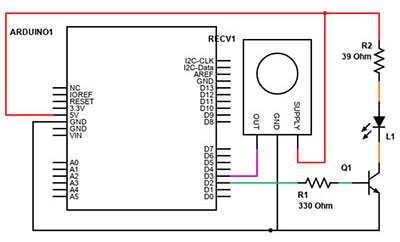
The schematic for this project is not very complicated, so building and understanding it shouldn’t be a problem, even for beginners. The circuit consists of an IR LED and an IR receiver. The Arduino is the component that’ll do most of the work.
I added a transistor that acts as an amplifier instead of using one of the Arduino’s GPIO pins to directly drive the LED. Doing so will also allow you to easily add an external power supply to boost the LED’s range, which can be useful in some applications. Anyway, I added a resistor to both the IR LED and the transistor to ensure that they operate correctly and within specifications:
The Software Part of this Project
As mentioned above, the circuit for this project is quite simple. That is because the software does the heavy lifting. The main idea behind the code is that Arduino sends out a quick pulse via the IR LED. The IR sensor detects that pulse, and the Arduino can measure the time between sending out a pulse and receiving an answer.
Remember the first part of the series of articles that discuss how IR communications work. There, I discussed that, unlike simple light sensors, IR receivers filter out IR sources that constantly emit IR radiation. They do so to ensure that only relevant information gets through, and other constant IR emitters, such as incandescent light bulbs, for example, don’t interfere with IR communication. Therefore, it’s impossible to detect obstacles by continuously leaving the IR LED switched on and assuming that there’s no obstacle between the LED and the sensor as long as the IR receiver detects some IR input. The LED has to pulse on and off to allow the IR sensor to detect it. When the IR sensor stops detecting these pulses, we can assume that there’s an obstacle in the way.
The following Arduino sketch implements this behavior:
#define IR_RECV_PIN 3
#define IR_SEND_PIN 2

unsigned long send_time = 0UL;
unsigned long recv_time = 0UL;

// Function prototypes
void falling_edge_detected(void);
void wait(unsigned long milliseconds);
void pulse_LED(int led_pin, unsigned long duration);

void setup()
{
  // Initialize the serial monitor. use a baud rate of 9600 bps
  Serial.begin(9600);

  // Initialize the I/O pins
  pinMode(LED_BUILTIN, OUTPUT);
  pinMode(IR_SEND_PIN, OUTPUT);
  pinMode(IR_RECV_PIN, INPUT);

  // Attach an interrupt to the IR receiver's data pin
  // The purpose of this is that the Arduino is going to call the falling_edge_detected
  // method whenever it detects that the IR receiver outputs a LOW signal instead of HIGH
  attachInterrupt(digitalPinToInterrupt(IR_RECV_PIN), falling_edge_detected, FALLING);

  Serial.print("Ready!");
}

void falling_edge_detected(void)
{
  recv_time = millis();
}

void pulse_LED(int led_pin, unsigned long duration)
{
  digitalWrite(IR_SEND_PIN, HIGH);

  wait(10);

  digitalWrite(IR_SEND_PIN, LOW);

  wait(10);
}

void wait(unsigned long milliseconds)
{
  unsigned long start = millis();

  while(millis() - start < milliseconds);
}

void loop()
{
  // Get the time just before sending out the pulse over the IR LED
  send_time = millis();
  // Pulse the IR LED on and off for 10ms (10ms on, 10ms off)
  pulse_LED(IR_SEND_PIN, 10);

  // When the sensor can see the LED (i.e. there's no obstacle between the sensor and the LED)
  // Then the interrupt method will record the current send time and d contains a positive number
  // that describes how long it took until the sensor could see the short pulse of the LED
  // This number is typically small (practically always very close to zero).
  unsigned long d = recv_time - send_time;

  // Then check whether the sensor detected the pulse 'in time'.
  if(recv_time >= send_time && d <= 2)
  {
	Serial.print(send_time);
	Serial.print(", ");
	Serial.print(recv_time);
	Serial.print(", ");
	Serial.println(d);
	digitalWrite(LED_BUILTIN, LOW);
  }
  else
  {
	Serial.println("Obstacle detected!");
	digitalWrite(LED_BUILTIN, HIGH);
  }

  // Wait before performing the next check
  wait(250);
}
The setup method initializes the relevant I/O pins. Note that the sketch doesn't configure the IR sensor’s data pin as a simple input. Instead, the setup function configures the receiver pin to listen for falling edges. Whenever the IR sensor detects a valid IR pulse, such as the ones from the Arduino, it pulls its data line low. Then, the Arduino detects the data line went low, and it calls the falling_edge_detected method. That method only sets a variable to a value that describes when the sensor detects the most recent pulse.
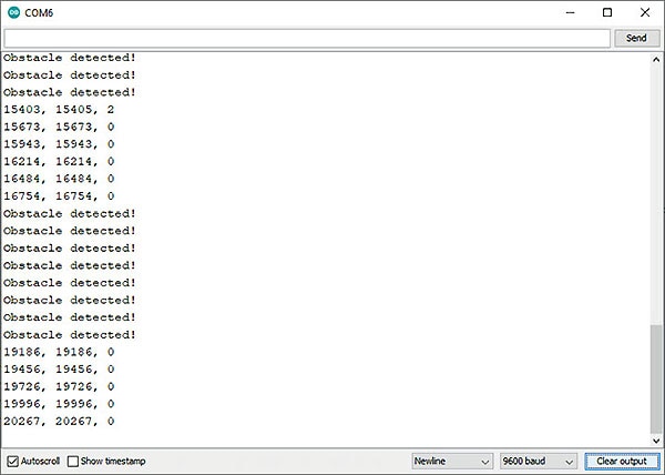
The loop method first records the current time in each iteration before sending out a short burst over the IR LED. After that, the loop method calculates how long it took the IR receiver to notice the pulse. Next, it checks whether the receive time was larger than the send time. If this check fails, then it means that the sensor didn’t receive a valid pulse within the timeout period. Otherwise, the loop method also verifies that the difference between the two times is less than two. If both conditions evaluate to true, then there was no obstacle between the LED and the sensor. Otherwise, we can assume that something got between the LED and the receiver.

Summary
Obstacle detection with the help of an IR LED and a matching receiver can be a useful tool in many applications. The circuit for this project is simple. It consists of an IR LED, a matching sensor, a transistor, and two resistors. The software turns the LED on and off in brief intervals, and then it checks whether the IR sensor noticed the pulse. Note that it’s impossible to leave the LED on and try to detect when something is blocking it because IR receivers typically ignore IR inputs that are always on.


Have questions or comments? Continue the conversation on TechForum, DigiKey's online community and technical resource.
Visit TechForum


 中国
中国