How to Make an LED Flasher Using a Raspberry Pi
2018-10-24 | By Maker.io Staff
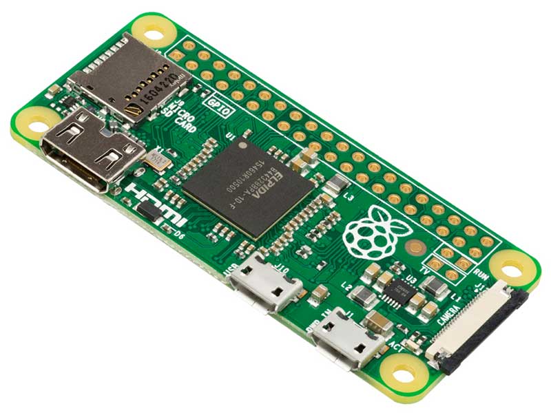
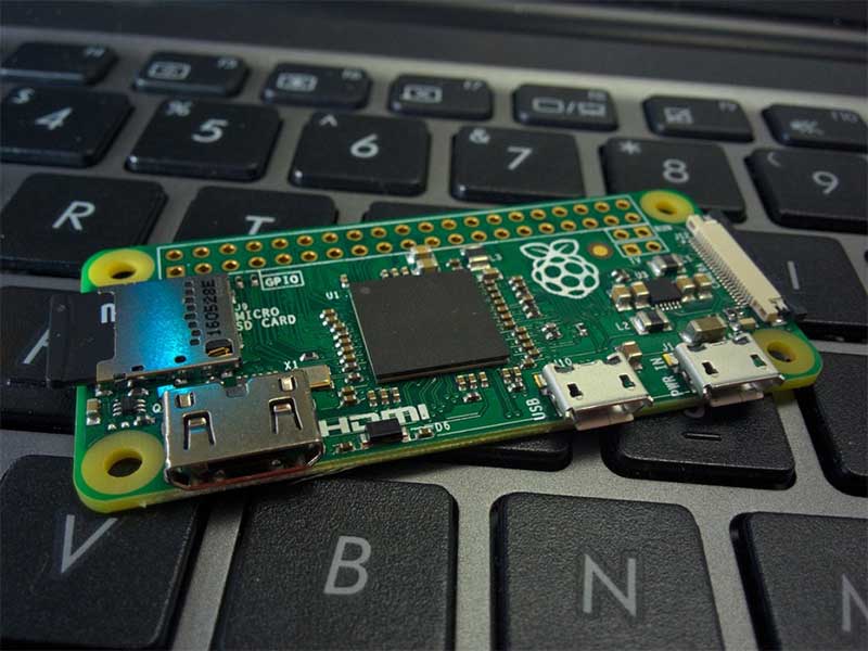
The Raspberry Pi has many features found on modern desktop computers, including graphics, large RAM sizes, and a decent processor. But the Raspberry Pi also features GPIO, which allows us to connect it to external circuits. In this how-to article, we will learn how to make a simple LED Raspberry Pi flasher!
BOM
Scheme-It

You can see a sample Scheme-It schematic for this how-to article here.
Python and GPIO
The Raspberry Pi has a 2 x 20 header. This is commonly referred to as the GPIO, which stands for general purpose input output. These individual connectors can link to external circuits, whereby they can either control circuits to, for example, enable/disable power to a device, or read from circuits (such as the state of a switch). The GPIO can be accessed using most languages, including C, C++, and Java, but one of the easiest languages to use is Python.
By using Python, you combine the power of a desktop computer with the functionality of a microcontroller, resulting in an incredibly versatile and customizable DIY system. So, let’s see how to use GPIO on the Raspberry Pi to create a simple LED flasher!
Python3 Editor and Raspbian
For this project, we will be using Raspbian, as it has a lot of preinstalled software and packages that are incredibly useful when creating hardware projects. The IDE that we will be using in this tutorial will be Python3 (IDLE), as it has the needed libraries preinstalled, in addition to just being simple. So, with your Raspberry Pi set up and loaded on the desktop, you will need to navigate to Pi > Programming > Python3 (IDLE).
GPIO Library
To use GPIO on the Raspberry Pi, we need to use the RPi.GPIO library, which comes preinstalled with Python3 IDLE (hence why we are using it). So, to start, create a new file, save this file as “flasher.py”, and then add the code below to the first line.
import RPi.GPIO as GPIO
This piece of code imports the RPi.GPIO library and then designates the word “GPIO” to mean the RPi.GPIO library. We use “as GPIO” so that we can use “GPIO” instead of “RPi.GPIO”, which is easier to read and write.
Next, we must set the board mode to either BOARD or BCM. This instruction is incredibly important because the Raspberry Pi has two numbering systems for the 40 GPIO pins. The first system, BOARD, defines each pin by its number, such that the first pin on the header is pin 1 and the last pin is pin 40. The second system, BCM, defines the pins by their GPIO number on the chip. For example, GPIO4 has BCM number 4 but is found on pin 7 on the PCB. This is somewhat bizarre, so it’s best to stick to BCM and use the diagram below to see the different GPIO numbers.

You can read a bit more on the GPIO on Raspberry Pi’s website.
So, to set the board numbering system to use BCM, we use the following command:
GPIO.setmode(GPIO.BCM)
The last step involves configuring the GPIO pin to be an output. When a GPIO pin is configured as an output, it can be used to either output 3.3V or 0V. When the pin outputs 3.3V, it is “on” (also referred to as a 1), and when the pin outputs 0V it is “off” (also referred to 0). The following instruction will configure GPIO14 to be an output, so we can turn the LED on and off! Note, GPIO14 is pin 8 on the Raspberry Pi header!
GPIO.setup(14, GPIO.OUT)
Making Our LED Flash!
With the pin configured and ready to go, you would think that we can dive straight into this LED program. Well, before we can, we need to do a few design checks to make sure that we will not damage our Raspberry Pi! The GPIO on the Pi cannot be used to source or sink much current (less than 50mA), and therefore, connecting GPIO configured as outputs directly to power or ground can be disastrous. Series resistors are put into circuits to prevent too much current draw, and series resistors should almost always be used with devices such as LEDs (the number of Pi projects online that do not include series resistors with LEDs is terrifying). This is why our schematic has a 1K resistor in series with the LED. Knowing the forward voltage drop of a typical 3mm red LED, we can calculate the current draw from our LED!
I=(VCC-Vf)R=3.3V-1.8V1000=1.5V1000=1.5mA
Now that we have confirmed that our circuit will not damage the Pi, let’s get this LED flashing!
To turn GPIO14 on, we use the following command:
GPIO.output(14, GPIO.HIGH)
To turn GPIO14 off, we use the following command:
GPIO.output(14, GPIO.LOW)
Making the LED flash is simple to do. Just use an infinite while loop and a second delay between the two functions shown above!
Python Code
import RPi.GPIO as GPIO
import time
GPIO.setmode(GPIO.BCM)
GPIO.setup(14, GPIO.OUT)
while(True):
# Turn on the LED and pause for one second
GPIO.output(14, GPIO.HIGH)
time.sleep(1)
# Turn off the LED and pause for one second
GPIO.output(14, GPIO.LOW)
time.sleep(1)


