Zener Diode Regulator with Transistor Current Buffer
2015-08-26 | By Maker.io Staff
Linear regulators are power sources that are well suited for applications in which tight regulation is not required, but low cost, low complexity, or low noise are important, or which require little power. This can be done with a simple circuit using a resistor, Zener diode, and transistor.
Zener diode basics
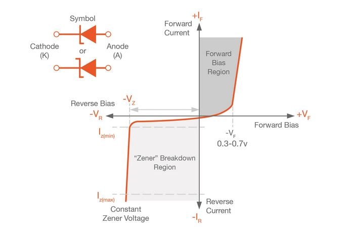
A Zener diode is designed to operate in reverse bias, clamping the voltage across its terminals to the Zener voltage. The Zener voltage is the voltage at which the Zener diode conducts current when reverse biased. Figure 1 shows two Zener diode circuit symbols and the current-voltage plot of a Zener diode. The voltage across the terminals will be nearly constant between the breakdown current—or “knee current”—Iz(min) and the maximum current rating Iz(max).

Figure 1: Zener diode current-voltage characteristics
Image Source:http://www.electronics-tutorials.ws/diode/diode_7.html
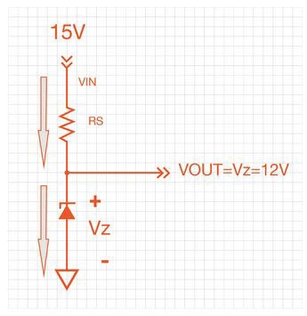
In real applications a resistor is used to limit current flow through a Zener diode, as shown in figure 2.

Figure 2:Simple resistor and Zener diode regulator
Resistor selection
The 3SMAJ5927B is a 12 V Zener diode in a 3 W package. It’s knee current, breakdown current, or minimum current is 0.25 mA. The maximum current is calculated by dividing the power rating by the Zener voltage: I=P/V = 3W/12V = 0.25A. In this case, the datasheet specifies 250 mA as the maximum current, so the calculation wasn’t necessary.
If we’re using the S3MAJ5927B to create a 12 V reference from a 15 V power source, as shown below, we can calculate the minimum and maximum values for the current limiting resistor Rs using Ohm’s law.
Minimum resistor value: Rmin=(Vs-Vz)/Izmax=(15V-12V)/0.25A=12Ω
Maximum resistor value: Rmax=(Vs-Vz)/Izmax=(15V-12V)/0.25mA=12kΩ

We should use a resistor value smaller than 12kΩ if there will be any load attached, but we should use as large a resistor value as possible to keep heat generation in the Zener to a minimum. The amount of heat generated in the Zener is P=VI.
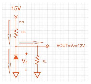
When we attach a load, RL, we must recalculate the value of the current limiting resistor Rs.

This is done by applying KCL to the circuit (Iz=Is-IL). Calculate the load current you need, then size the resistor to keep the Zener current between its minimum and maximum.
If the load resistor RL were 500Rmin=(Vs-Vz)/Izmax=(15V-12V)/0.25A=12Ω, then the load current is 12/500=24 mA. The maximum resistor value has to allow 24 mA + 0.25 mA = 24.25 mA current to flow. Applying Ohm’s law, R=V/I, we get R=(Vs-Vz)/Izmax=(15V-12V)/24.25mA=123.7Ω.
Resistors should be chosen to allow enough current to flow to the load and to the Zener in order to allow for regulation, but not much more. The resistors’ physical size will depend on the amount of heat dissipated in the resistor.
The Zener diode should be chosen for Zener voltage, and also for the power rating and package size. Package size is related to heat dissipation. Choose a package with a power rating large enough to keep operating temperatures below datasheet maximum (ideally, much lower).
Image current capability with a current buffer
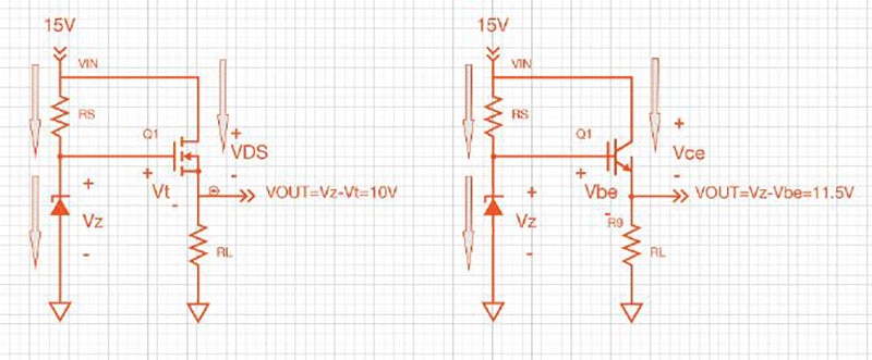
The Zener regulator has a high source impedance—because all load current must travel through Rs—limiting the amount of current that the regulator can provide to the load. Overcome this limitation by buffering the output of the Zener diode with a source follower, as shown in figure 5.

Figure 5:Buffered Zener regulator circuits
This regulator has low output impedance, meaning that the voltage will not droop much with load. This circuit can be built with a MOSFET or a BJT. The output voltage is Vz-Vt for a Zener regulator with a MOSFET buffer, or Vz-Vbe for a Zener regulator with a BJT current buffer. In this case, the current limiting resistor can be much smaller. For the MOSFET buffer, little more than the Zener knee current is required. For the BJT buffer, the Zener current + the load current divided by the DC current gain of the BJT is required. The heat dissipated in the MOSFET buffer is P=VDS*IL. Similarly, the heat dissipated in the BJT current buffer is P=Vce*IL. Choose a MOSFET or BJT in a package that is large enough to handle the power.
Conclusion
This article has covered the basics of biasing a Zener in the reverse bias regime to create a simple linear regulator. The drawback of the basic regulator, mainly a high source impedance, is overcome with a transistor current buffer.

Have questions or comments? Continue the conversation on TechForum, DigiKey's online community and technical resource.
Visit TechForum


 中国
中国