


制造商零件编号 2163
SOLDERING IRON 50W 120V
Adafruit Industries LLC
License: See Original Project Arduino Adafruit Feather
Courtesy of Adafruit
Guide by Collin Cunningham
Overview
Technology connects us to the outer world, but have we lost touch with our inner selves? Let's attempt to remedy this modern condition by controlling room lighting & sound with the beating of your own heart. Hey - it's worth a shot.
This project uses a Pulse Sensor Amped, Feather M0, MusicMaker FeatherWing, RGB LED strips, and power MOSFETs to turn any room into a thumping, flashing pulse room. For a more refined version of this idea in a gallery setting, see Sean Montgomery's excellent Emergence installation.
What you'll need
Basics:
Feather Parts:
LED Driver Parts:
Software
The code for this project is based off the Pulse Sensor Amped's Arduino sketch. Modifications have been made to include audio file playback, timer interrupts on the Feather M0, and serial output has been removed to keep things simple.
First, install the latest version of the Arduino IDE, if you haven't already:
Install Adafruit SAMD Boards
Open the Arduino IDE and go to Tools->Board->Boards Manager... and use the search box to find "SAMD". First, ensure that Arduino SAMD Boards is not installed (if it is installed, remove it). Then select Adafruit SAMD Boards, click the Select Version pulldown menu, select version 1.0.13. Click the Install button and wait for the process to complete.
Install Libraries
Next, you'll need a couple of Arduino libraries. The first one can be installed via the Arduino IDE's library manager. Go to the Sketch->Include Library->Manage Libraries... Search for "VS1053" and install the Adafruit VS1053 Library.
Next, download the Adafruit ZeroTimer library from GitHub:
Download Adafruit Zerotimer Library.zip
Unzip the downloaded archive, and rename the resulting folder to "Adafruit_ZeroTimer" (just remove the "-master" string). Once the folder is renamed, move it to your Arduino library folder (Documents/Arduino/libraries) and restart the Arduino IDE.
You'll also need the Adafruit_ASFCore library, which is available here:
Unzip the downloaded archive, and rename the resulting folder to "Adafruit_ASFcore" (just remove the "-master" string). Once the folder is renamed, move it to your Arduino library folder (Documents/Arduino/libraries) and restart the Arduino IDE.
Download project code & upload to Feather
Grab the Pulse_Room project code from GitHub:
Unzip the downloaded archive and rename the resulting folder to Pulse_Room. Inside the folder, you'll find the Pulse_Room.ino file - open it in the Arduino IDE.
Connect your Feather M0 board via USB. Go to Tools->Board and select Adafruit Feather M0 (Native USB Port) from the list. Then go to Tools->Port and select the port for your Feather M0. Click the Upload button and wait for the process to complete.
Sound File
Now that the Feather is programmed, we can put our sound file on an SD Card for playback. You could use your own sound file, or the one I used named beat1.mp3, which is included in the Pulse_Room zip file downloaded in the previous step. More info on compatible file formats can be found in the MusicMaker FeatherWing guide.
Copy the file to the root level of your Micro SD card. Note that your SD card should be formatted for FAT16 or FAT32 and have a capacity greater than 64MB.
Feather Connections
About those headers…
In order to have access to the Feather M0's prototyping area, I decided to mount the MusicMaker Wing underneath the Feather. I also wanted to easily connect & disconnect the Pulse Sensor - so this means we'll need female headers on both the M0 & MusicMaker Wing.
Solder the stacking female headers (headers with longer pins) to the Feather M0.
Solder the regular female headers to the MusicMaker FeatherWing.
Once complete, your boards should look something like this …
Mount components on Feather M0
We'll be adding two components to the Feather M0's prototyping area:
Here's a schematic showing all the connections we'll make to the Feather (including the Pulse Sensor Amped).
Position the terminal block and slide switch on the Feather's prototyping area and solder them in place.
Solder the bottom 3 pins of the terminal block to GND and solder the top 2 pins together (we'll connect these to pin 11).
Use solid core hookup wire to connect the M0's Pin 12 to the center pin of the switch and solder the switch's bottom pin to GND.
Use another hookup wire to connect the M0's Pin 11 to the top 2 pins of the terminal block. Solder the terminal blocks
For reference - below is a shot of the feather after soldering is complete. Note the use of the GND bus conveniently located in the Feather's prototyping area:
To avoid mistakes later, use a marker or paint to label the terminal block's ground connections.
Connect it all
Connect the Feather M0 on top of the MusicMaker FeatherWing and make sure they're securely mounted.
Connect the Pulse Sensor Amped to the Feather M0:
Pop the SD card into the MusicMaker Wing, and you're good to go.
LED Driver
The LED driver board will take the 3.3 V PWM signal from the Feather M0 and use it to control 12 V power needed for the LED strips. One board connected to a 12V 1A power supply is capable of pulsing the red channel of two 5-meter LED strips without the need for a heatsink.
The board itself is quite simple. Check out the schematic below:
We put down a 1 Megaohm resistor for the pulldown resistor but later found 10 Kohm works better!
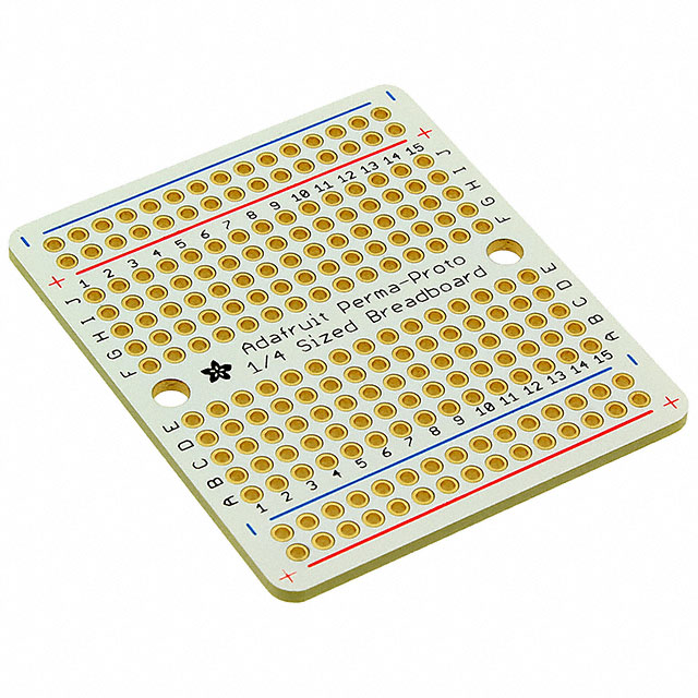
Component layout
Place the components on the Perma-Proto board, solder, and trim any protruding leads.
Solder wire jumpers
Solder the necessary connections between components using solid core hookup/jumper wire. Check the image below to reference what connections need to be made:
The finished board should look something like this:
Label the terminal block
Label the terminal block to avoid incorrect connections. You can use a marker, paint, or the best of both worlds - a paint marker.
Since we're only using the red channel of the LED strips, each 12V LED Driver board will be able to power 2 x 5-meter strips. Build additional boards as needed …
Wiring
A whole lotta wire…
Determine where you'd like to place the Feather + Pulse Sensor in your room and then decide where you to place the LED driver boards + LED strips. I placed the Feather near the middle of the room on a coffee table and the driver boards on opposite walls – so I needed a lot of wire to connect the Feather to each driver (~20ft to allow for routing around furniture/etc).
Each board needs 2 connections - one for PWM signal, and one for ground. 2-conductor cable, such as a thin coaxial type, would be ideal for this situation. I had 26AWG stranded wire on hand, so that's what's used in this guide.
Figure out the length you'll need, then cut two matching lengths of different colored wire (I used black for ground & yellow for PWM)
Strip about 1/4 inch of insulation off the ends of each wire, then tin the tips with solder.
Optionally, to keep the wires from getting too unruly, you can twist the pairs together and bind them at regular intervals with tape or heat shrink tubing …
Extend the LED Strip Wires
The wires coming off the LED strips aren't very long, so you'll likely need to solder extensions to them. Since we're only using the red channel, we only need to extend the red & black wires.
The color coding on the strip's wires is a bit confusing. The red wire is a ground/negative connection for the red channel and the black wire is the positive/12V connection for the whole strip. Because these colors were the opposite of conventional designation, I swapped them when extending. Hopefully, this does not make things even more confusing for those following along.
Cut two pieces of stranded wire for the extensions - ~4ft worked for me. Strip and solder the tips.
Solder the extensions to the LED strip's wires and seal the connections with heat shrink tubing or electrical tape.
The tail end of the LED strip also has wire leads for chaining strips (an option I did not explore). To avoid shorts, wrap the red and black wires on that end with a couple layers of electrical tape…
Installation & Usage
Mount LED strips & drivers
The LED strips have an adhesive backing which is handy for mounting but could potentially damage some delicate surfaces. If you wish to minimize adhesive contact, leave the paper backing on the strips and use pieces of double sided or gaffers tape at ~1ft intervals.
You could also simply hang them around like Christmas lights - experiment to see what you like the best.
These LEDs are quite bright and looking at them directly can be rough on the eyes.
To minimize harshness, mount the LEDs around molding, behind furniture, or facing upward above eye level - this will create a pleasantly diffused and ambient effect.
Mount the LED driver boards on the wall or somewhere close enough to connect to the LED strip's wires. Insert the wires into the driver board's terminal block and screw them into place.
Don't connect power to the boards just yet!
Final Connections
Connect power to the Feather M0 via the USB jack or JST battery connector and connect audio to your amplifier via the MusicMaker wing's 3.5mm jack.
Insert and screw down ground & PWM wires on the Feather and connect them to the LED driver boards.
Finally, Connect 12V power to the LED driver boards.
Use it.
See the Pulse Sensor Amped guide for specifics on wearing the sensor. I found attaching it to my thumb with the included velcro strips produced the most reliable, steady connection.
The red LED on the Feather M0 will flash at every beat detected. Once you see a relatively slow, steady flashing, you'll know you have a good connection to the pulse sensor.
Once you have a steady pulse shown on the Feather's LED, go ahead and flick the switch on the Feather and witness your pulse displayed at room scale …
Now sit and ask yourself, "Why did I do this?" and suddenly remember – art serves no practical purpose. It's just cool.

Have questions or comments? Continue the conversation on TechForum, DigiKey's online community and technical resource.
Visit TechForum


 中国
中国