Building a Voice-Controlled Robot - Diving into the Circuits
2024-07-29 | By Annabel Ng
S1XT33N Project
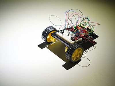
As mentioned in a previous blog post, UC Berkeley’s EECS 16B course has a strong focus on the semester-long project of building a voice-controlled robot called S1XT33N. However, this robot isn’t your standard robotic car that you might’ve built in middle or high school. My lab partner and I were only given the basic 2-wheel robot components including the wheels, motors, chassis, Arduino Leonardo, batteries, and breadboard, and we had to build and wire everything else ourselves. If you're interested in learning more about the course, check out the course website at https://www.eecs16b.org/.
Here is a summary of everything I learned in the labs, which is all credit to the lovely course EECS 16B course staff. Some of the circuit components we had to wire included motor encoder circuits, a voltage regulator circuit, a microphone board circuit, and a low pass filter to isolate our voice frequencies. We also had to program different feedback systems to implement motion for our car, including open and closed-loop feedback. After adding in motion, we recorded our voice commands and designed our PCA classification algorithm so our voice commands would match with specific motions. The most important part of the project was integrating everything into a cohesive voice-controlled robot. Another key part of this project was learning to build planar circuits and debug complex systems.
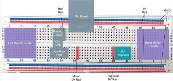
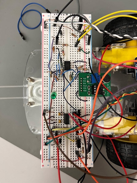
This is the layout of the breadboard with all the different circuits.
Motor Control and Motor Encoder Circuits
The first step in building the robot was to give the robot’s Arduino control over the motors and allow for the wheels to move. When supplying voltage to the motors, we will be using the Pulse Width Modulation (PWM) pin from the Arduino. We want to supply voltages between 0 and 5V to the motors, but it's difficult to supply DC currents at specific values like 3.3 V, for example. To get around this, we use PWM signals with “duty cycles” that represent the percentage of time the signal is powered on, allowing us to control the average voltage of the PWM signal. Different duty cycles allow us to achieve different specific voltages, thus allowing for control over the motors.
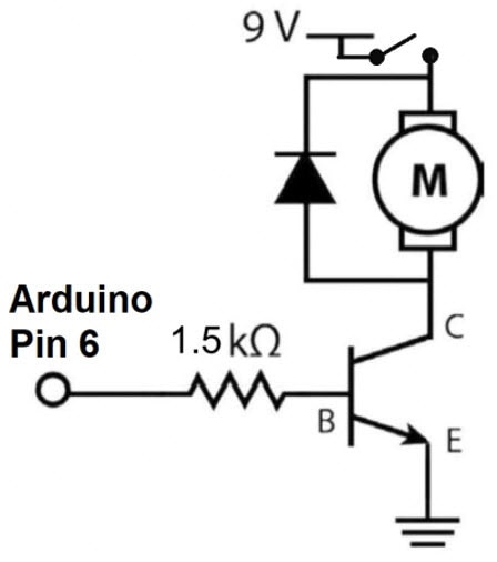
However, each motor needs a separate controller circuit which consists of an NPN Bipolar Junction Transistor (BJT), diode, and resistor. The role of the NPN BJT is to function as a voltage-controlled switch. When the BJT is on, it can be seen as effectively connecting our power source to ground which “completes the circuit.” The BJT also handles more current than the Arduino pins, which allows the necessary current to enable the motor to run. The resistor value controls the amount of current going into the base terminal of the BJT, and as the value of the resistor increases, the current decreases. The diode conducts the current in a specific direction and helps to dissipate the back EMF generated by the inductive behavior of the motor. After building a controller circuit for each wheel, each circuit is connected to the 9V power rail through a single switch to control whether the motors are on or off.
Here's the circuit layout of a motor controller circuit. The Arduino pin on the left supplies the PWM signal, the component with an M is the motor, and the BJT is below the motor acting as a switch.
After testing the controller circuits, the next step is to build the encoder circuits to allow the robot to measure the distance traveled by each wheel. The encoders use a light-based mechanism to measure velocity. They emit light between two components and, when connected to the robot wheel, calculate the velocity by recording the number of light interruptions within a specific timeframe. This method allows for precise and accurate velocity measurements. This will become very important when implementing the control feedback schemes for traveling along predefined paths. I got one encoder for each wheel and connected the encoders to the breadboard and Arduino with braided jumper wires to shield the signal wire from external noise. Since the encoder outputted a higher voltage than the Arduino could handle, I built a voltage divider to reduce the encoder output voltage before connecting it to the Arduino.
Voltage Regulator Circuits
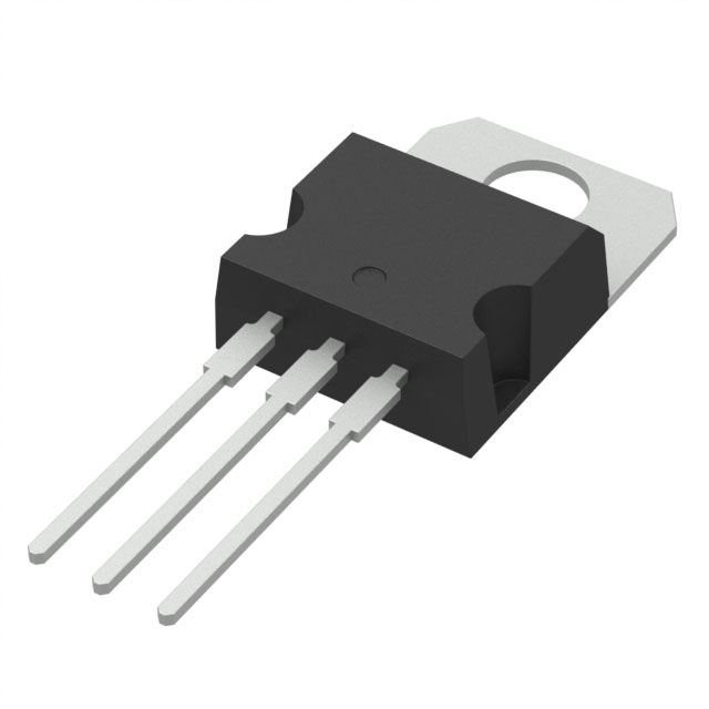
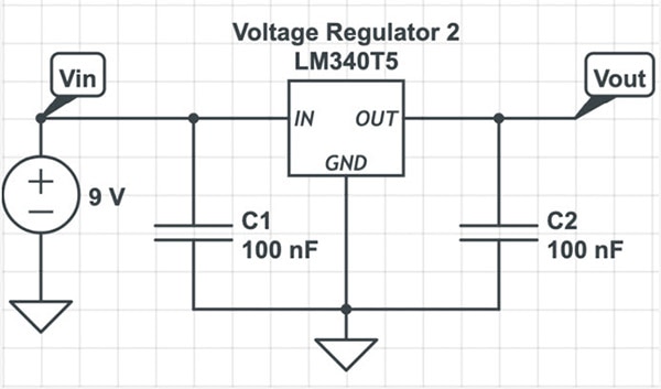
At this point, our robot can control its motors and also measure the velocity of each wheel. The next step is to build a voltage regulator circuit. The supplied batteries are 9V, but the robot’s circuits take in 5V. To lower the voltage to the necessary 5V, I used a 5V regulator alongside two 100 nano-farad capacitors to help the robot reduce high-frequency noise and stabilize the voltage fluctuations on the rails.
Here's the circuit layout of the voltage regulator circuit.
Microphone biasing circuit
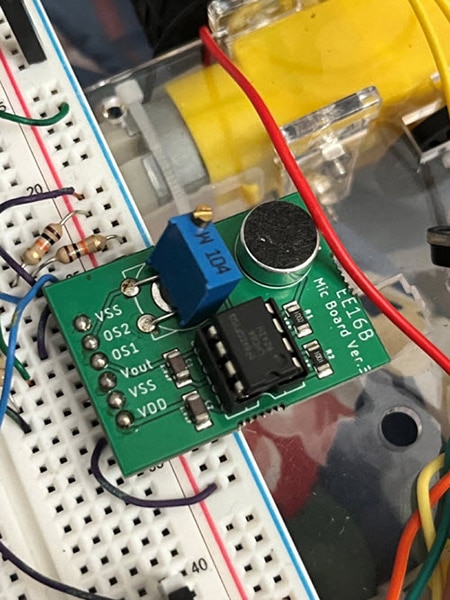
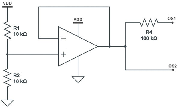
Students are provided with a printed circuit board (PCB) for the microphone board, but before I could use the microphone board for the robot, I had to set up the mic board with a biasing circuit to provide signals for the different pins in the mic board. The biasing circuit establishes predetermined voltages at various points in the circuit. The first pin served as the DC offset to help center the signals between 0 and 5V, and the second pin served as a “virtual ground.” This virtual ground allowed me to establish a half rail with a voltage of 2.5V. After building the biasing circuit to process voice signals, I tuned the mic board by playing tones at different frequencies and adjusting the potentiometer until the peak-to-peak voltage didn’t exceed 5V for all valid frequencies.
Here's the custom microphone printed circuit board, which consists of an electret mic, a potentiometer, an op-amp socket, as well as ground and 5V pins. Below is the schematic for the mic biasing circuit.
Low pass filter
Since the robot should process voice signals and not random noise, I built a low pass filter to isolate the frequencies below a specific cutoff frequency to help better sample voice commands. The first step was to identify a good cutoff frequency. Conversational speech frequencies range around 3 kilohertz, so I set that as my cutoff point. The lowpass filter consists of a resistor and capacitor, and I used a resistor of 6200 ohms and a capacitor of 10e-9 farads, giving a cutoff frequency of 2570 Hz by the formula freq=1/2piRC. The peak-to-peak voltage at the cutoff frequency point should be 1/rad(2) original peak-to-peak voltage, and I verified this with a function generator. Since the signal of the lowpass filter was weak, I built a non-inverting amplifier with a gain of 2 to strengthen the signal.
Here's an example of an RC low-pass filter.

Here's the final breadboard!
These were all of the main circuit components of S1XT33N, and at this point, the robot can pick up voice signals and move the wheels. However, the robot cannot travel in a straight line, recognize specific words, or move after a specific voice command. That’s for the next blog post, focusing on control systems, PCA, and integration! All credit for figures is to course staff from https://www.eecs16b.org/.


