Teaching Electronics to Absolute Beginners
2020-03-02 | By Clive Maxfield
Breadboards Wearables Arduino FLORA
I have many friends who have no knowledge whatsoever regarding electronics and computers. This is only fair, since I typically have little familiarity with their areas of expertise. Most of the time, the fact that we follow our own paths is of no account; every now and then, however, our respective spheres collide, as it were.
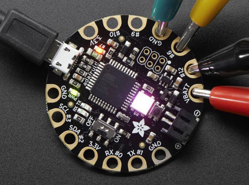
Such an occasion occurred recently when a trio of my friends—Goodly Juju, Ronnie, and Saar—asked me to teach one of them "how to make LEDs flash." These guys, who are all amazing artists, have an office in the next building over from mine. One of their activities is to screen print their original art on t-shirts. A few weeks ago, they started looking at the NeoPixel-based products from Adafruit, such as the FLORA Wearable Electronic Platform, which can be used to drive hundreds of NeoPixels (Figure 1).

Figure 1: The FLORA Wearable Electronic Platform is a round, sewable, Arduino-compatible microcontroller that can drive hundreds of tri-colored NeoPixel LEDs and is designed to empower amazing wearables projects. (Image source: Adafruit)
These guys help me out all the time. Goodly Juju (Goodly for short) is a photographer, so if I need a professional image taken for something or other, he will bring his green screen and lighting and suchlike over to my office and snap away. So, of course, I said yes.
In fact, Goodly is the member of their merry band who has been designated to "learn the trade" (Figure 2). We commenced by chatting about what he knew about electronics and computing. It didn't take long for me to realize that we were going to have to start at ground zero.

Figure 2: Goodly Juju and your humble narrator (I'm the one in the Hawaiian shirt). In return for all of the photographic and artistic help Goodly and his friends provide, I'm teaching Goodly about electronics and Arduino. (Image source: Max Maxfield)
We began by considering the topic of voltage, current, and resistance. Of course, this required us to briefly discuss atoms (protons, neutrons, electrons), molecules, and ions. We also introduced the concept of conductors and insulators. Once we were comfortable with the idea of electricity being the migration of large numbers of electrons from a source to a target, we began to discuss the relationship between voltage, current, and resistance. For this, I always like to start with a water analogy (Figure 3).

Figure 3: A water analogy provides a useful way to introduce the relationship between voltage, current, and resistance. Voltage equates to the height of the water; resistance is inversely proportional to the area of the hole; and current equates to the amount of water flowing at any particular time. (Image source: Max Maxfield)
If I was doing this with someone younger, we would actually get a large plastic bottle, mark the side with an indelible marker, and have a happy time spraying water everywhere. In the case of Goodly, it was sufficient to draw a picture.
In this analogy, the voltage (electrical potential) equates to the height of the water in the bottle, while the current equates to the amount of water flowing through the hole at any particular time. The tricky thing is conveying the idea that the resistance to the flow is inversely proportional to the area of the hole.
This leads us to Ohm's law, which defines the relationship between these three quantities in a steady state system: V = I x R (voltage equals current times resistance). Of course, it also forces us to explain why we measure voltage in volts (in honor of the Italian physicist Alessandro Volta) and use the symbol V, why we measure current in amperes, or amps, (in honor of the French mathematician and physicist André-Marie Ampère) and used the symbol I (not A), and why we measure resistance in ohms (in honor of the German physicist Georg Simon Ohm) and use the symbol Ω. (It's funny how complicated this is when you try to explain it to someone else.)
The great thing about this water analogy is that it's easy to wrap one's brain around the fact that doubling the voltage will double the current, while doubling the resistance will half the current, and so forth.
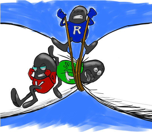
Another great visual for this sort of thing is the classic "three characters and a pipe." I'm sure most engineers have seen this a thousand times. Unfortunately, I don't know who created the original in order to ask permission to use it. Thus, I turned to Ronnie (introduced earlier), who whipped up a custom representation for me (Figure 4).

Figure 4: A "Cool Beans" representation of voltage (V), current (I), and resistance (R). The current character is being pushed through the pipe; the voltage character is the one doing the pushing; and the resistance character is restricting the current character's ability to move. (Image source: Max Maxfield)
Since I'm often heard to say, "Cool Beans," Ronnie created these characters as anthropomorphic beans (you don’t see many of those these days). The idea is that the voltage character is trying to push the current character through a pipe (or wire in the case of an electrical circuit), while the resistance character is devoted to impeding things.
This also proves to be a good time to point out that in the same way that the resistance in our earlier water analogy is inversely proportional to the area of the hole in the bottle, so too the resistance in an electrical circuit is inversely proportional to the cross-sectional area of the wire (I know, this is a gross simplification, but it works as a starting point).
Our next step will be to move to a simple LED and current limiting resistor circuit. For this we could use something like an LTL-10223W red LED from Lite-On Inc.; a CF14JT150R 1/4 watt, 150 Ω, 5% tolerance resistor from Stackpole Electronics Inc.; and a GS-830 breadboard from Global Specialties.
For power and ground, we would probably use an A000073 Uno from Arduino, along with a couple of 759 male-male breadboard jumper wires from Adafruit. I personally think this is a good way to introduce the Arduino Uno into the picture, but it's important to make clear to the student that—at this stage—we are only using it as a power supply.
This will involve explaining things like the reason it's important to choose a color code for one's wiring and stick to it (I prefer green for ground and red for 5 volts). We will also discuss the fact that the LED only conducts electricity in one direction and how to determine the anode (long lead) from the cathode (flat side on package). This will also provide a good excuse to introduce resistor color codes and tolerances, as part of which we will calculate the value of our current limiting resistor.
Once we have gotten our first LED to light up, the world is our oyster (or lobster, or crustacean of our choice).
Conclusion
It's funny, but you only realize how much you know (and how much you don’t know) when it comes to explaining something to someone. I'm already planning out a series of future lesson plans, but I would welcome your comments and suggestions.


