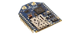
Real Time Location System (RTLS)
 Figure 1: RTLS applications (Image Source: DecaWave)
Real-time location systems (RTLS) which enable devices to determine location, is gaining popularity. The RTLS market share is growing rapidly because of the enhanced capability of real-time tracking in a variety of markets including agriculture, building control and automation, factory automation, healthcare, safety and security, warehousing and logistics, and a range of others.
Advantages of RTLS include accuracy, increased productivity, and operational excellence to track desired objects. RTLS also provides some additional benefits, such as improvement in safety and security of staff, efficient and effective logistic and supply chain operations, and smooth process operations. The most common example of RTLS is GPS, which can make it easy to find your way in a foreign country on roads you’ve never seen before. However, GPS doesn’t work indoors, so all the tracking and location functionality that GPS provides suddenly disappears when stepping into a building.
There are many different methods of implementing RTLS using wireless solutions. In general, two common methods are:
1. RSSI (Received Signal Strength Indicator) – based on radio signal strength
2. TDoA (Time Difference of Arrival) – based on radio signal travel time between transmitter and receiver.
 Figure 2: RSSI measurement (Image Source: DecaWave)
RSSI
Received Signal Strength Indicator (RSSI) is a measurement of the power present in a received radio signal. In an IEEE 802.11 system, RSSI is the relative received signal strength in a wireless environment. Therefore, the higher the RSSI number, the stronger the signal.
RSSI is fairly simple to implement, but it is sensitive to a multi-path signal and interference. Additionally, using RSSI to compute location typically involves a location survey when installing reference points (APs). To get high levels of RSSI accuracy, it requires additional technologies (like choke points and infrared etc.), but those will increase the total cost of the solution.
TDoA
Time Difference of Arrival (TDoA) is a time-based method to measure the accurate propagation time of the radio signal from one area to another. Three or more readers are positioned in known locations around the area in which tagged items are to be located.
When the tagged object communicates with each of the fixed anchors in what’s called a Two-Way Ranging exchange, the tag and each anchor exchange timing information so that the anchor can calculate the time of flight of the signal from the tag to the anchor without needing the tag and anchor to be synchronized in time. Once each anchor has this information, a location engine can calculate the position of the tagged object. This requires the tag to be capable of receiving as well as transmitting, which means that this method generally consumes more power than the Time Difference of Arrival solution we’ll see in the next section.
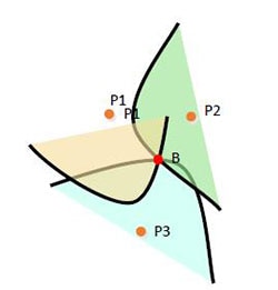 Figure 3: TDoA with at least 3 visible access points (Image Source: DecaWave)
In this method, the tag (B) communicates individually with each of the three anchors (P1, P2 & P3). Each anchor calculates the time of flight of the transmission from the tag. In order to calculate the distance between the tag and an anchor, a two-way exchange of messages between the tag and each anchor is involved. A very simplified version of what happens is as follows:
1. The anchor transmits a message to the tag and records the time the message left its antenna (let’s call it t1).
2. The tag receives the message and sends back a reply.
3. The anchor records the time it receives the reply (let’s call it t2).
4. The anchor then calculates the time difference Tr = t2 – t1.
5. The anchor then calculates the distance using the formula d = cTr/2, where c is the speed of light.
This is what’s known as Two-Way Ranging.
In reality we also need to count the processing delay in the tag, and there are many methods that can be adopted to both take this delay into account and to minimize it.
The total time between the two time-stamped values can therefore be expressed as: -
TT = 2Tt + TTA
where TT is the total time
Tt is the time of flight of the signal
TTA is the turnaround time in the tag
Implement Two-Way Ranging with Evaluation Kit
The DecaWave TREK1000 is a Two-Way-Ranging RTLS Evaluation Kit which leverages the DecaWave DW1000 IEEE802.15.4-2011 UWB compliant wireless transceiver IC. The TREK1000 contains four EVB1000 evaluation boards and software source code (Figure 4). Implementing the software code with the kit can reduce your time to develop your own RTLS.
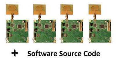 Figure 4: DecaWave TREK1000 (Image Source: DecaWave)
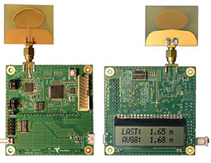 Figure 5: EVB1000 component side and display side (Image Source: DecaWave)
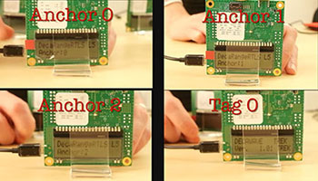 Figure 6: Get Started with TREK1000 (Image Source: DecaWave)
If you want to expand the system with more anchors and tags units, you can choose the DecaWave EVK1000 Evaluation Kit (which contains two EVB1000 evaluation boards) for your design. The TREK1000 allows evaluation in tracking, geo-fencing, and indoor navigation.
1. Tracking — Three anchors and tag(s) can add tracking in logistics and factory automation. In Figure 7, it can determine the 3D position of the tag relative to the fixed anchor’s position.
 Figure 7: Tracking in TREK1000 (Image Source: DecaWave)
2. Geo-Fencing (also called 'Secure Bubble') — This is based on one anchor and up to three tags as shown in Figure 8. It can enable you to see if the tags are within certain pre-defined perimeters around the anchor, like a secure bubble. It is good for personal safety (collision avoidance, security perimeter around machinery), child monitoring, and ‘secure-my-valuables’ in applications.
 Figure 8: Geo-Fencing in TREK1000 (Image Source: DecaWave)
3. Navigation — Three anchors and tag(s) are configured as shown in Figure 9. Connected directly to the tag, the user will be able to walk around and visualize its current position for testing human and robotics navigation scenarios.
 Figure 9: Navigation in TREK1000 (Image Source: DecaWave)
IEEE 802.15.4-2011 UWB (Ultra-Wideband)
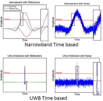 Figure 10: Narrowband and UWB in multipath and interference (Image Source: DecaWave)
UWB is a good solution to realize RTLS and can obtain accuracy information. IEEE 802.15.4-2011 UWB uses radio waves with very short impulse transmissions. Its short bursts of signals, with sharp rises and drops, makes the signals’ starts and stops inherently easier to measure.
In an UWB solution, the pulses are very narrow (2 ns). There is only a very small group of multipath signals, where the path length is within 2 ns of the direct path length and is capable of causing interference at the receiver. In general, the multipath signals will all have less energy than the direct path signal.
The multipath signals all have a path length between receiver and transmitter that is longer than the direct path. They therefore arrive later in time than the direct path. It is this property that allows us to distinguish the direct path from the later-arriving multipath and thereby calculate the correct time of flight between the transmitting and receiving nodes. This means that the distance between two UWB devices can be measured precisely by measuring the time that it takes for a radio wave to pass between the two devices.
DecaWave DW1000 is an IEEE802.15.4-2011 UWB compliant wireless transceiver IC, and the world's first single chip UWB transceiver, enabling you to develop cost effective RTLS solutions with a precision of 10 cm indoors, even while moving at up to 5 m/s.
Conclusion
UWB provides attractive benefits to offer RTLS radio transmission using very narrow pulses. Its precision technology offers a cost-effective implementation of standard based solutions.
Reference:

Have questions or comments? Continue the conversation on TechForum, Digi-Key's online community and technical resource.
Visit TechForum


