Use Specialized MCUs to Simplify Motion-Control Design
投稿人:DigiKey 北美编辑
2016-09-07
Digital motion control methods offer precision regulation of movement and positioning of electric motors and actuator driving end effectors in robotic systems. In practice, however, engineers developing motion control systems based on conventional proportional-integral (PI) controllers typically find their projects stalled as they struggle to tune sensitive controller parameters. A more effective approach reduces tuning complexity while delivering stable performance across a wide range of operating conditions.
Low-cost, high-performance microcontrollers have fueled the rapid emergence of digital motor control able to respond to a wide range of operating conditions through software control. By designing PI controllers in software, engineers could create highly responsive motor control systems with a minimum number of components. In practice, however, finding the optimal set of PI controller parameters presents developers with significant challenges. Too often, engineers find that the unique characteristics of each motor (and associated motor control system implementation) significantly complicates the task of ensuring stable operation of the motor across varying speeds and loads. As a result, the motor-control development team find themselves forced to extend project schedules and resolve subtle tuning problems.
PI controller challenges
A conventional PI controller uses a control loop that generates an output intended to reduce the error between intended values and measured values in some process. In the serial form of the control loop (Figure 1), Kb sets the zero of the PI controller while Ka sets the bandwidth of the closed-loop system response.

Figure 1: In the serial form of the conventional PI controller, engineers must find the optimal settings for its zero (Kb) and bandwidth (Ka) -- a process that often delays motion-control projects. (Image source: Texas Instruments)
In motor control applications, the complexity of PI controller optimization becomes more complicated as engineers need to control current to control speed. In a typical motor-speed control loop, engineers would use two PI controllers -- one in an inner loop to control motor current, the other in an outer loop to control motor speed (Figure 2). When the motor speed falls below the commanded value, the outer loop calls for more current; the inner loop corrects motor current to match the desired value.

Figure 2: A typical speed control loop uses two PI controllers to control motor current and the speed itself, compounding the task of finding optimal controller parameters. (Image source: Texas Instruments)
In practice, achieving stable performance across operating conditions becomes a complex, time-consuming task. Engineers need to adjust multiple parameters to tune the controller for a specific speed and load operating point. Yet, a specific tuning solution might address only a very small range of speed and load. Consequently, engineers may find that a highly dynamic system with different speed and load points may require tuning a PI controller for each point, further delaying the project schedule.
Advanced control algorithm
The TI InstaSPIN-MOTION solution provides a significantly simpler approach to digital motor control design. At the heart of InstaSPIN-MOTION, SpinTAC from LineStream Technologies provides robust control across dynamic speed, position, and load ranges of the system. This proprietary approach provides advanced speed and position control and features active disturbance rejection control (ADRC).
ADRC accommodates a high degree of uncertainty in motor models. It treats unmodeled motor dynamics and undesired behavior of the system as a disturbance that can be estimated, rejected or corrected. This allows SpinTAC controllers to control a wide range of positions, speeds and loads with a single tuning parameter, called bandwidth, which determines the stiffness of the system and dictates how aggressively the system will reject disturbances.
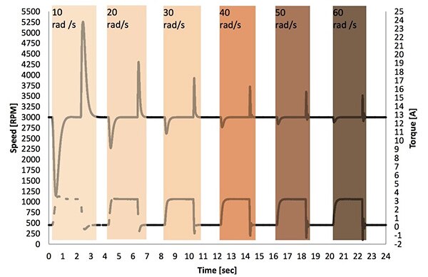
As the designer increases the controller's bandwidth with this tuning approach, the response to a torque disturbance becomes faster and has less overshoot (Figure 3). If the bandwidth is set too high, the system begins to oscillate around the target speed when the torque disturbance is removed from the system. The designer only needs to find the bandwidth that results in minimal oscillation around the target speed value when the torque is removed.

Figure 3: SpinTAC tuning requires setting only one parameter – bandwidth. In this example the ideal bandwidth is 40 rad/s. At that bandwidth, the response exhibits minimal oscillation around the target speed when the torque is removed. (Image source: Texas Instruments)
Simplified development
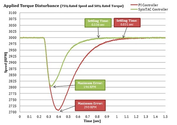
Rather than deal with the complexity of optimizing multiple parameters in conventional PI controllers, InstaSPIN-MOTION lets engineers tune their system simply by setting the single bandwidth parameter. This simple yet robust approach can dramatically reduce development time compared to designs using conventional PI controllers. At the same time, this approach delivers a solution that features less overshoot and faster settling time, resulting in an overall reduction of power consumption by the end applications (Figure 4).

Figure 4: In response to an applied torque disturbance, InstaSPIN recovers significantly more quickly than a traditional PI controller loop. (Image source: Texas Instruments)
TI further offers an extensive platform for development and deployment that combines software and hardware. TI's MotorWare offering includes device-specific drivers and support software as well as complete system examples and technical training.
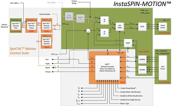
For faster deployment of these designs, TI offers specialized versions of its C2000 Piccolo MCUs that include InstaSPIN-MOTION libraries in on-chip ROM and Flash with no extra charge (Figure 5). Based on a 90 MIPS C28x processing core, the C2000 InstaSPIN TMS320F28069M MCU combines the on-chip InstaSPIN-MOTION motor control software with a full complement of on-chip peripherals including a 16-channel analog-to-digital converter (ADC) for acquiring the data used in the motor control algorithm (for example, see ADC input show in the right side of Figure 5).
Figure 5: Texas Instruments’ TMS320F28069M MCU features the InstaSPIN-MOTION software libraries on chip, further simplifying development of motion control systems. (Image source: Texas Instruments)
The TMS320F28069M also features eight on-chip enhanced pulse-width modulator (ePWM) modules, providing 16 PWM channels. As a result, engineers can quickly design complete motor control systems with minimal additional components. The MCU's PWMs can directly drive specialized isolated gate drivers such as the TI ISO5851 (Figure 6). The ISO5851 features CMOS inputs, enabling the microcontroller to drive them directly -- unlike typical optocoupler-based gate drivers, which need external current drivers and biasing circuitry to provide the input control signals.

Figure 6: Paired with a highly integrated microcontroller such as the TI TMS320F28069M, CMOS isolated gate drivers such as the TI ISO5851 allow designers to create sophisticated motor control systems with a minimal number of additional components. (Image source: Texas Instruments)
On the software side, motor control implementation is similarly straightforward thanks to the SpinTAC controller algorithm. Engineers configure SpinTAC velocity control with a minimal number of steps starting with including an appropriate header file (e.g., spintac_velocity.h) to bring the SpinTAC software components into the application. (This example addresses SpinTAC velocity control but SpinTAC position control configuration follows a similar approach.)
Developers then declare the global structure in the main source file:
ST_VelCtl_t stVelCtl; // The SpinTAC Speed Controller object
ST_VELCTL_Handle stVelCtlHandle; // The SpinTAC Speed Controller Handle
In the main function of the application, developers would then initialize configuration variables to their default values. For many motors, this configuration would typically include the following variables:
Copy
ST_VelCtl_t stVelCtl; // The SpinTAC Speed Controller object
ST_VELCTL_Handle stVelCtlHandle; // The SpinTAC Speed Controller Handle
In the main function of the application, developers would then initialize configuration variables to their default values. For many motors, this configuration would typically include the following variables:
// Initialize the SpinTAC Speed Controller Component stVelCtlHandle = STVELCTL_init(&stVelCtl, sizeof(stVelCtl));
// Setup the maximum current in PU
_iq maxCurrent_PU = _IQ(USER_MOTOR_MAX_CURRENT / USER_IQ_FULL_SCALE_CURRENT_A);
// Instance of the velocity controller
STVELCTL_setAxis(stVelCtlHandle, ST_AXIS0);
// Sample time [s], (0, 1)
STVELCTL_setSampleTime_sec(stVelCtlHandle, _IQ(ST_SPEED_SAMPLE_TIME));
// System inertia upper (0, 127.9999] and lower (0, SgiMax] limits [PU/(pu/s^2)] STVELCTL_setInertiaMaximums(stVelCtlHandle, _IQ(10.0), _IQ(0.001));
// System control signal high (0, OutMax] & low [OutMin, 0) limits [PU] STVELCTL_setOutputMaximums(stVelCtlHandle, maxCurrent_PU, -maxCurrent_PU);
// System maximum (0, 1.0] and minimum [-1.0, 0) velocity [pu/s] STVELCTL_setVelocityMaximums(stVelCtlHandle, _IQ(1.0), _IQ(-1.0));
// System upper (0, 0.2/(T*20)] and lower [0, BwScaleMax] limits for bandwidth scale STVELCTL_setBandwidthScaleMaximums(stVelCtlHandle,
_IQ24((0.2) / (ST_SPEED_SAMPLE_TIME * 20.0)), _IQ24(0.01));
// System inertia [PU/(pu/s^2)], [SgiMin, SgiMax]
STVELCTL_setInertia(stVelCtlHandle, _IQ(USER_SYSTEM_INERTIA));
// Controller bandwidth scale [BwMin, BwMax]
STVELCTL_setBandwidthScale(stVelCtlHandle, _IQ24(USER_SYSTEM_BANDWIDTH_SCALE));
// Initially ST_VelCtl is not enabled
STVELCTL_setEnable(stVelCtlHandle, false);
// Initially ST_VelCtl is not in reset
STVELCTL_setReset(stVelCtlHandle, false);
During operation, the main interrupt service routine would update the speed reference, acceleration reference and speed feedback and then call the SpinTAC velocity control function at a decimation rate (specified in ISR_TICKS_PER_SPINTAC_TICK ) appropriate for the part.
Copy
CTRL_Obj *obj = (CTRL_Obj *)ctrlHandle; // Get pointer to CTRL object
// Get the mechanical speed in pu/s
_iq speedFeedback = EST_getFm_pu(obj->estHandle); // Get the mechanical speed in pu/s // Update the Velocity Reference
STVELCTL_setVelocityReference(stVelCtlHandle,
STVELMOVE_getVelocityReference(stVelMoveHandle));
//Update the Acceleration Reference
STVELCTL_setAccelerationReference(stVelCtlHandle,
STVELMOVE_getAccelerationReference(stVelMoveHandle));
//Update the Velocity Feedback STVELCTL_setVelocityFeedback(stVelCtlHandle, speedFeedback); // Run the SpinTAC Speed Controller STVELCTL_run(stVelCtlHandle);
// Get the Torque Reference from the SpinTAC Speed Controller
iqReference = STVELCTL_getTorqueReference(stVelCtlHandle);
// Set the Iq reference that came out of SpinTAC Velocity Control
CTRL_setIq_ref_pu(ctrlHandle, iqReference);
Developers can jump-start motor-control development with the TI C2000 Piccolo F28069M LaunchPad, which features all the hardware and software necessary to develop applications based on the F2806x microprocessor. TI also offers complete motor-control solutions kits such as the High Voltage Motor Control Kit, which offers a comprehensive introduction to control of the most common types of high voltage, three phase motors, including AC induction (ACI), brushless DC (BLDC), and permanent magnet synchronous motors (PMSM). TI also offers complementary kits such as the BLDC Motor Kit, which includes a brushless DC motor with built-in Hall-effect sensors, which works with the motor control kit software right out of the box.
Conclusion
Conventional motor control design using conventional PI controllers can face significant delays due to the complex process of tuning these controllers. Built into specialized microcontrollers, TI's InstaSPIN-MOTION reduces tuning to a single parameter, offering designers a combination of simplicity and stability that makes it ideal for applications such as robotic systems that exhibit multiple state transitions or experience dynamic changes.

免责声明:各个作者和/或论坛参与者在本网站发表的观点、看法和意见不代表 DigiKey 的观点、看法和意见,也不代表 DigiKey 官方政策。


 中国
中国