How to Quickly Add Environmental Sensing Industrial IoT Designs
投稿人:DigiKey 北美编辑
2017-12-20
The ability to measure environmental parameters can serve as the basis for building sophisticated wellness and safety features into factory and industrial applications, as well as smart buildings, appliances, and personal products. However, to provide these features and help meet regulatory requirements, developers need to find a means of efficiently merging results from multiple sensors that minimize space, power, and cost, while ensuring maximum accuracy, precision, and reliability.
To accomplish this, developers can now turn to sophisticated sensor fusion algorithms that are able to generate information about air quality, temperature, humidity, and overall comfort.
This article will show how this can be done with minimal effort using a single device and software from Bosch Sensortec, specifically, the BME680 and its associated support hardware and software.
Regulations driving air sensor development
Health and comfort levels are closely bound with environmental factors in ways that go well beyond simple measurement of basic parameters. Human sense of a comfortable temperature depends not just on temperature, but on the humidity level as well. Health experts combine temperature and humidity into a “heat index” that warns of significant health risks at high levels. As the heat index predicts, humans working in an environment at a given temperature can face significant health risks as humidity rises (Figure 1).
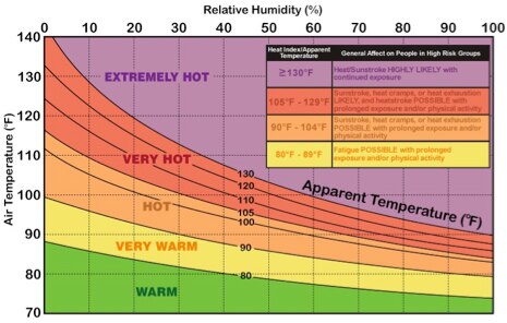
Figure 1: Humans are affected by combinations of temperature and relative humidity, making it more useful to measure them concurrently. (Image source: United States National Weather Service)
Human factors experts go further, defining a subjective “comfort zone” based on a new parameter of “effective temperature”, which combines temperature and humidity into a single index. Changes in temperature or humidity can quickly result in an environment that feels uncomfortable to a typical individual (Figure 2).
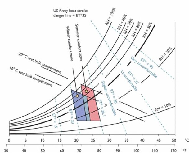
Figure 2: Humans perceive a comfort zone bounded narrowly by variations in temperature and relative humidity that in the extreme can result in significant health risks including heat stroke. (Image source: Federal Aviation Administration)
As with heat index, dramatic changes in temperature, humidity, or both outside the comfort zone can quickly create a situation that is more than just uncomfortable. Above a temperature dependent level of humidity, individuals can even face danger of heat stroke. The concept of comfort zone in work environments is so important that its operating parameters are specified in Standard 55 of the American Society of Heating, Refrigeration and Air Conditioning Engineers (ASHRAE), approved by the American National Standards Institute (ANSI).
Although significant excursions outside the comfort zone can impact health, even relatively modest changes in effective temperature can impact human performance. In a survey of experimental studies on this topic, researchers found a consistent degradation in work performance outside a relatively narrow band of effective temperature (Figure 3).
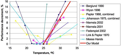
Figure 3: Researchers consistently find that performance drops when effective temperature falls outside a relatively narrow range. (Image source: Lawrence Berkeley National Laboratory)
At the same time, temperature and humidity are by no means alone in impacting health and wellness. Arising from multiple natural and man-made sources, volatile organic compounds (VOCs) represent a particularly insidious threat to air quality. Because of the critical importance of air quality for health, organizations such as the US Environmental Protection Agency (EPA) collapse the various parameters that define air quality into a single index (Figure 4). Typically presented as a health indicator for cities and larger geographical areas, the air quality index (AQI) finds direct application in microclimates, buildings, and other high occupancy areas. Sophisticated heating, ventilation, and air conditioning (HVAC) systems in large buildings often rely on some measure of air quality as part of their airflow process control designs.
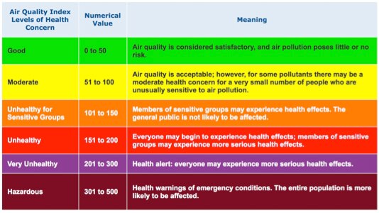
Figure 4: Environmental and health organizations use a standard air quality index to warn local populations of air quality conditions that can give rise to a range of health risks. (Image source: United States Environmental Protection Agency)
For engineers, the complex interrelationships between basic factors such as temperature, humidity, and VOCs translate into significant challenges for the design of health and wellness sensing systems. At the most fundamental level, designers must accurately measure each of these factors.
In the past, developers solved these types of sensing problems by combining transducers with custom signal chains for processing the raw voltage and current output. The emergence of smart sensors dramatically simplified development of sensing systems. By integrating the transducer, sensor signal chain, analog-to-digital-converter (ADC) and control logic, smart sensors can deliver accurate, temperature compensated digital sensor data to a host MCU. Developers only need to connect these devices to MCUs through SPI or I2C interfaces commonly supported by the integrated sensor.
Still, for derived analyses such as comfort zone and AQI, even a collection of individual smart sensors falls short of delivering an effective solution. Also, the use of multiple sensors results in greater design complexity, a larger BOM, and a larger physical footprint. This compromises developers’ abilities to meet customers’ demands for smaller, more efficient designs.
Perhaps worse, designs that use multiple sensors, even smart sensors, face significant problems in meeting functionality requirements. Deriving a measurement, even as fundamental as effective temperature, requires developers to synchronize underlying sensor measurements for use in sensor fusion algorithms. The Bosch Sensortec BME680 removes these design constraints, allowing developers to use a single device and an associated sensor fusion library to rapidly meet the requirements for health and wellness applications.
Integrated smart sensors
The BME680 is an integrated environmental sensor that combines temperature, humidity, pressure, and gas sensors in an 8-pin LGA package measuring only 3 x 3 x 1 mm. In particular, the device’s gas sensor supports air quality measurements based on measurement of a wide range of gases.
The device achieves high linearity and accuracy while consuming only microamps (µA) of power in normal operation, and only 0.16 μA in sleep mode. During typical operation, the BME680 consumes only 1.0 μA for temperature measurements. For combined measurement of humidity, pressure and temperature, the device uses only 3.7 μA. For gas sensing, the nature of the sensor subsystem results in power consumption ranging from 0.09 milliamps (mA) to 12 mA, depending on operating mode.
The higher power consumption for gas sensing results from a two-phase process. The gas sensor itself is a metal oxide-based device that undergoes a change in its resistance when it comes in contact with a wide variety of VOCs, or other ambient contaminants. Before the sensor can operate, however, a heater in the gas sensor subsystem increases the temperature to a level required to ensure accurate measurement. Within the gas sensor subsystem, a heater control block uses a control loop to control output from an integrated digital-to-analog converter (DAC). In turn, the DAC output is used to adapt the amount of current injected into a resistive heater element to increase the temperature.
The BME680 provides developers with several methods for controlling power consumption associated with gas sensing. Using three different operating modes, developers can trade update rate for power consumption. For applications that require maximum update rates, the gas sensor can operate in a continuous mode that updates every second and consumes 12 mA.
For applications with lower update requirements, developers can opt for two different modes. In low-power mode, the gas sensor updates its readings every 3 seconds (s), consuming 0.9 mA in the process. For applications where power limitations outweigh update rate, developers can operate the gas sensor in its ultra-low-power mode, which consumes only 0.09 mA but updates once every 300 seconds.
Besides their difference in update rate and power consumption, these two modes differ significantly in the response time of the gas sensor. In low-power mode, the gas sensor subsystem features a typical response time of 1.4 s. Ultra-low-power mode results in a significantly slower response time, typically 92 s.
Developers can also exercise some level of control on power consumption by controlling the heating process. Typically, to achieve the desired temperature level, the device requires about 30 ms of heating prior to gas sensor measurement. Developers can control the heating duration – and affect power consumption – by programming the heating duration in a range from 1 ms to 4,032 ms.
Sensing sequence
To avoid unnecessary power consumption, the BME680 starts up in sleep mode, waiting for a measurement command. In most cases, developers operate the device in forced mode, which causes the device to automatically sample each of its sensors sequentially (Figure 5).

Figure 5: In its forced mode operating state, the Bosch Sensortec BME680 sequentially samples its temperature, pressure, and humidity sensors before heating the gas sensor, prior to sampling. (Image source: Bosch Sensortec)
In forced mode, the device completes measurements from its temperature, pressure, and humidity sensors before performing the heating required prior to gas sensor measurement. During the heating phase, the heating element typically reaches target temperatures between 200°C and 400°C, and maintains that temperature for the programmed heating duration. By performing this heating phase only after the initial sensor measurements, the device avoids any direct impact of the heating element on those sensor measurements. Finally, after the heating phase reaches the specified duration, the device’s ADC generates the gas sensor resistance value.
The BME680 signal chain provides developers with methods for optimizing certain measurements. To reduce measurement RMS noise, developers can program the device to oversample its temperature, humidity, and pressure sensors. There is also an option to enable an integrated infinite impulse response (IIR) filter to reduce the effect of transient events on temperature and pressure sensor measurements. Although the internal IIR filter reduces the bandwidth of those measurements, it boosts their resolution from 16 bits to 20 bits. Note that due to their measurement methodology, this type of filtering isn’t necessary for humidity and gas sensors.
Besides configuring the measurement process for sensors, designers can separately enable or disable measurement of individual temperature, humidity, and pressure sensors. However, Bosch Sensortec recommends that developers always enable temperature measurement because the associated software packages use temperature data to correct other sensor measurements.
Although oversampling and filtering can reduce noise and enhance resolution, the final output of the BME680 ultimately takes the form of uncompensated sensor values produced by the device’s internal ADC. Developers need to apply calibration parameters stored in the device to produce accurate results. Fortunately, the device drivers include an application programming interface (API) that handles that task.
Design and development with the BME680
To help kickstart designs, Bosch Sensortec provides a complete driver and API that simplifies software development for designs using the BME680. For basic operations such as data compensation, developers need only call separate API functions for each sensor. For example, the calc_gas_resistance function's calling parameters include the gas sensor ADC output and a BME60 data structure (Listing 1) used to access calibration data stored in the device.
struct bme680_dev {
/*! Chip Id */
uint8_t chip_id;
/*! Device Id */
uint8_t dev_idDK;
/*! SPI/I2C interface */
enum bme680_intf intf;
/*! Memory page used */
uint8_t mem_page;
/*! Ambient temperature in Degree C*/
int8_t amb_temp;
/*! Sensor calibration data */
struct bme680_calib_data calib;
/*! Sensor settings */
struct bme680_tph_sett tph_sett;
/*! Gas Sensor settings */
struct bme680_gas_sett gas_sett;
/*! Sensor power modes */
uint8_t power_mode;
/*! New sensor fields */
uint8_t new_fields;
/*! Store the info messages */
uint8_t info_msg;
/*! Burst read structure */
bme680_com_fptr_t read;
/*! Burst write structure */
bme680_com_fptr_t write;
/*! Delay in ms */
bme680_delay_fptr_t delay_ms;
/*! Communication function result */
int8_t com_rslt;
};
Listing 1: The Bosch Sensortec open-source BME680 driver provides all the basic software support for interacting with the BME680, and illustrates key software structures which contain key configuration values. (Code source: Bosch Sensortec)
Based on the parameters stored in the device, the function returns the corrected gas sensor result (Listing 2).
static uint32_t calc_gas_resistance(uint16_t gas_res_adc, uint8_t gas_range, const struct bme680_dev *dev)
{
int64_t var1;
uint64_t var2;
int64_t var3;
uint32_t calc_gas_res;
var1 = (int64_t) ((1340 + (5 * (int64_t) dev->calib.range_sw_err)) *
((int64_t) lookupTable1[gas_range])) >> 16;
var2 = (((int64_t) ((int64_t) gas_res_adc << 15) - (int64_t) (16777216)) + var1);
var3 = (((int64_t) lookupTable2[gas_range] * (int64_t) var1) >> 9);
calc_gas_res = (uint32_t) ((var3 + ((int64_t) var2 >> 1)) / (int64_t) var2);
return calc_gas_res;
}
Listing 2: The BME680 driver includes sensor specific routines such as this function, which converts raw gas sensor data to calibrated readings using sensor calibration data stored within the device. (Code source: Bosch Sensortec)
As noted earlier, however, more useful quantities such as effective temperature, comfort level, and air quality are derived algorithmically from raw temperature, humidity, and gas sensor data. For example, air quality depends not just on VOC readings from the gas sensor but also on effective temperature, which depends on temperature and humidity results from those sensors. Adding to this algorithmic complexity, natural drift in sensors mandates periodic use of calibration methods to maintain accurate results. The Bosch Software Environmental Cluster (BSEC) software package addresses these concerns, enabling developers to easily generate the complex information required for health and wellness applications.
Building on the open-source BME680 driver set, BSEC is a closed-source binary package that implements the algorithms needed for sensor fusion. For example, using BME680 sensor readings, BSEC algorithms generate a metric for indoor air quality that reflects the standard air quality index shown in Figure 4.
Bosch Sensortec provides the BSEC as a binary distribution for major instruction set architectures including ARM® Cortex®-M, Espressif Systems ESP8266, and Renesas RL78 MCUs. The BESC distribution also includes C language header files for the BESC API as well as sample software that illustrates use of the BSEC sensor fusion API. For example, a sample main routine (Listing 3) demonstrates a complete sensor program using just two functions to initialize the device and periodically sample BME680 sensors.
int main()
{
/* Call to the function which initializes the BSEC library
* Switch on low-power mode and provide no temperature offset */
bsec_iot_init(BSEC_SAMPLE_RATE_LP, 0.0f, bus_write, bus_read, sleep);
/* Call to endless loop function which reads and processes data based on sensor settings */
bsec_iot_loop(sleep, get_timestamp_us, output_ready);
return 0;
}
Listing 3: The Bosch Software Environmental Cluster (BSEC) software distribution includes sample software such as this main routine illustrating device initialization and sensor sampling. (Code source: Bosch Sensortec)
Developers use the bsec_iot_init function to specify sample rate, a temperature offset, and the amount of time to sleep between samples. Two additional parameters, bus_write, bus_read, allow developers to swap in different bus access methods for reading and writing BME680 registers.
As part of their systems configuration, developers can specify their own software routines for bus writes and reads. For example, they can easily run the drivers or BESC package on an Arduino platform by using the Arduino Wire library for bus I/O (Listing 4). The drivers and BESC each use a device structure that contains pointers to those custom I/O routines. During program execution, working code performs bus operations using the software I/O routines referenced by those pointers in the device structure.
#include <Wire.h>
int8_t bus_write(uint8_t dev_addr, uint8_t reg_addr, uint8_t *reg_data_ptr, uint8_t data_len)
{
Wire.beginTransmission(dev_addr);
Wire.write(reg_addr); /* Set register address to start writing to */
/* Write the data */
for (int index = 0; index < data_len; index++) {
Wire.write(reg_data_ptr[index]);
}
return (int8_t)Wire.endTransmission();
}
Listing 4: With the Bosch Sensortec BME680 driver and BESC package, developers can use their platform specific bus I/O software routines such as this bus write routine, which uses the Arduino Wire library for operation on Arduino compatible hardware platforms. (Code source: Bosch Sensortec)
For the development platform itself, users can take advantage of Arduino compatible evaluation boards as well as boards available from Bosch Sensortec. The company’s BME680 shuttle board simply brings out the BME680 device’s VDD analog supply, ground, VDDIO digital supply, ground, and serial interface (chip select, serial data input, serial data output, serial clock input). Developers can use the shuttle board in their own custom MCU-based designs, or simply plug the shuttle board into Bosch Sensortec’s own Application Board.
For Arduino developers, the MikroElektronika MIKROE-2467 MikroBUS click board provides a simple option for connecting to compatible development boards. Along with the BME680, the click board adds a USB interface and supply voltage regulators. Developers can use the click board by itself, or plug it into MikroBUS compatible hardware such as the MikroElektronika MIKROE-2340 development board (Figure 6).
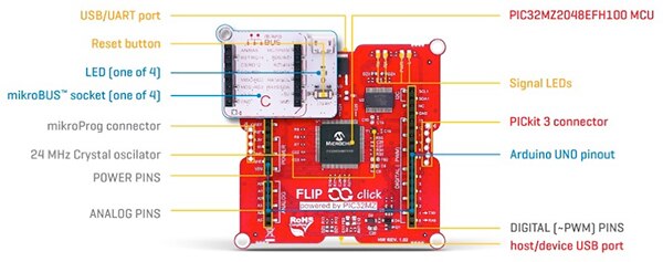
Figure 6: Developers can quickly begin developing BME680-based applications by plugging the MikroElektronika MIKROE-2467 MikroBUS click board into the MikroElektronika MIKROE-2340 development board, which provides MikroBUS connectors on one side of the board and Arduino connectors on the other. (Image source: MikroElektronika)
The board includes a Microchip Technology 32-bit PIC32MZ2048EFH100 MCU, which combines a high-performance MIPS32 M-class processor core, floating-point unit, 2 Mbytes of flash, 512 Kbytes of SRAM, a rich set of analog peripherals, and standard digital interfaces. Along with standard connectors, the MIKROE-2340 board brings out development ports and provides LEDs for simple user notification.
A unique feature of the board is its support for both MikroBUS and Arduino connectors, available on either side of this double-sided board. For software design, the board supports chipKIT, an Arduino compatible open-source embedded development environment. Using the familiar Arduino environment, designers can leverage the extensive Arduino ecosystem to rapidly implement environment sensing systems.
Conclusion
Used in combination with the Bosch Software Environmental Cluster and driver, the Bosch Sensortec BME680 dramatically reduces the complexity, cost and footprint of both hardware and software design for environmental sensing.
This combination provides a numerical assessment of air quality, effective temperature and comfort, allowing developers to create more sophisticated designs that meet health related wellness and safety requirements in industrial, city, and domestic applications.

免责声明:各个作者和/或论坛参与者在本网站发表的观点、看法和意见不代表 DigiKey 的观点、看法和意见,也不代表 DigiKey 官方政策。


 中国
中国