Expanding a Strong Foundation: “Ruggedizing” Connectors for Next-Gen Embedded Computing Applications
2016-03-01
Introduction
More. That’s the essence of “pushing the performance envelope.” For designers of embedded computer systems in military and aerospace applications, it means higher-speed processing to handle the ever-increasing complexity of signals intelligence and networked warfare. This, in turn, requires connectors not only capable of handling the high data rates, but also offering increased ruggedness to provide reliable operation in harsh environments.
Even as designers pursue higher processing loads and more rugged components, two other trends affect the design of connectors. The first is to address SWaP—size, weight, and power consumption—to create systems that are smaller, lighter, and more capable. In high-performance aircraft, whether manned or unmanned, where space is always at a premium, weight has a direct relationship to flight times and payload, and efficient power distribution helps allow for smaller power-generation components. Thus, it is no surprise that system designers are obsessed with SWaP.
The other important trend is the use of commercial off-the-shelf (COTS) components—ensuring product availability when you need it. Even a new design can be COTS-based by using well-established building blocks and field-proven technology.
New levels of connector ruggedization can take two forms: (1) an entirely new connector or (2) an upgrade to an existing connector. Option 1 gives the most freedom, but at the expense of legacy product designs and standards. Option 2 allows backwards compatibility with existing connectors and board designs.
The TE Fortis Zd connector is an example of Option 1. Even though the connector is relatively new, it has its roots in COTS. This connector, designed around military pedigree MIL-DTL-55302 Mini-Box contacts, is a new design that offers higher speeds (12+ Gb/s) and high levels of ruggedness. The connector has been considered for several standards, and finds applications where performance trumps meeting a standard.
An example of Option 2 is seen in TE’s MULTIGIG RT 2 connector, which is discussed in detail below.
Torture testing a connector design
For standards-based embedded computing, VITA 46 and 47 have been standards for measuring compliance and performance. These standards define mechanical systems packaging requirements as well as test requirements for shock, vibration, temperature, and other environmental stresses that systems in general and connectors in particular must withstand.
Ruggedized connectors, such as the MULTIGIG RT 2 connector specified for VITA 46 VPX systems, must meet VITA 47 requirements. More recently, some companies in the industry have looked to understand margin beyond VITA 47 to even more stressful testing of connectors. The VITA 72 Working Group has created new levels of testing—torture testing, as it were—connectors well beyond the needs of anticipated application hazards. In doing so, the tests led to improvements in connector design. One of the connectors tested was the MULTIGIG RT 2 connector.

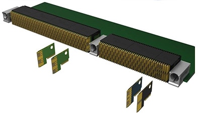
Figure 1: A typical VITA 46 6U VPX configuration uses the MULTIGIG RT 2 connector. The use of wafers in the MULTIGIG RT 2 daughtercard connector helps create a light weight, versatile, pinless connector design.
The connector uses a pinless design: wafers in the daughtercard half and split-beam, spring contacts in the backplane side. By eliminating pins and the problems of stubbing and bent pins, the pinless design helps to increase reliability and prevent damage during card handling and mating. The wafer-based design of the daughtercard allows each wafer to be individually configured: single ended, differential, power, or even hybrids. While VITA 46 specifies the types of connector modules for each module zone (P0- through P6), the wafer design gives designers the potential to mix and match wafers if necessary. A significant benefit for meeting SWaP issues is that the MULTIGIG RT 2 connector is the lightest VPX connector available—owing in large part to the lightweight wafer and connector construction.
Testing a connector’s mettle
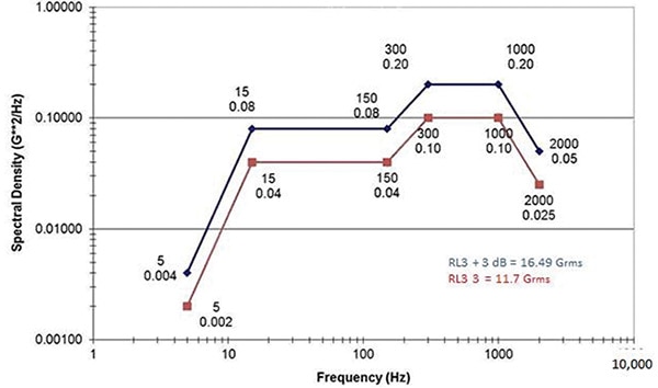
Figure 2 shows one of the major differences in vibration testing between the VITA 47 standard and VITA 72 requirements, based on testing criteria created by Mercury Systems and the VITA 72 Working Group. RL3 is essentially the same as VITA 47’s V3. RL3 + 3 dB substantially increases the vibration level. This higher power spectral density subjects connectors to much greater stress, increasing the potential for contact fretting and plating wear caused by the vibration-induced movement of contacts against each other. These higher vibration levels were also run for longer exposure times than in the prior VITA 46/VITA 47 testing. The general test sequence was:
- RL3 Random Vibration: 1 hour per axis
- RL3 + 3 dB Random Vibration: 1 hour per axis
- RL3 + 3 dB Random Vibration: 12 hours, Z axis

Figure 2: Testing performed by the VITA 72 working group subjected connectors to much more stressful testing with the RL3 + 3 dB level random vibration.
Upon examination of the product tested by the VITA 72 working group, the original MULTIGIG RT 2 connector performed remarkably well; however, select locations along the 6U card showed high levels of wear, suggesting an enhanced contact solution would be desired.
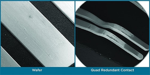
Conventional connector wisdom says increasing the points of contact at the separable interface is effective because multiple contact points provide redundancy, thus increasing the reliability of the connection. Some have suggested that the sweet spot is four points of contact. For example, if the probability of contamination affecting the contact resistance is, say, 0.01 on a given contact, the probability for all four points of a four-point contact being simultaneously affected is (0.01)4 or 10-8! This illustrates the power of redundancy. Part of the redesign included a major enhancement in the mated contact pairs while maintaining backward compatibility with the existing design. In the original connector, each contact spring beam makes a single point of contact with the wafer pads. In the newer version, the contacts have been redesigned so that each beam makes two points of contact—termed quad redundant—roughly doubling the contact patch area. Figure 3 shows the original and redesigned contacts.

Figure 3: Original and quad redundant MULTIGIG RT 2 contacts.
An important feature of the new enhanced design is that the contact beams and areas on the two beams are not symmetrical to one another. The difference in contact beam lengths means that each beam has unique frequency modes in response to vibration, helping to eliminate the possibility of both beams achieving a resonance simultaneously. Even with increased contact points, the new enhanced contact system does not increase mating forces while helping maintain reliable contact under extreme vibration levels.
The wafers in the mating half were also slightly modified to take full advantage of the new beam design. Because two of the four contact points on the split beams are deeper, the signal pads on the wafer were extended 1.2 mm to maintain at least 2 mm of contact wipe during mating, maintaining quad redundancy throughout the entire mating range of the original design.
Test results
Figure 4 shows the results of a 6U VPX module when “torture tested” to the levels as specified in Figure 2. To inspect for indications of contact wear, each connector module was dissected and visually reviewed for signs of contact wear on both the original and modified contact systems. Although most of the contacts in the 6U arrangement are able to withstand this extreme vibration environment, there are specific contact locations that are susceptible to fretting wear. Most importantly, the wear that was experienced with the original contact design practically disappears with the new quad-redundant design. Interestingly, the choice of guide hardware also influences performance.
The role of guide hardware in helping ruggedize a connector is often overlooked. The primary purpose of the hardware is to help the mating process by providing card slot keying and initial alignment of the connector halves. Many guide posts and modules are economically manufactured using a die cast process. To fulfill the keying and guiding function, post and receptacle can have fairly generous manufacturing tolerances common for die-cast parts. As a result, the guides play a reduced role in restricting motion during shock and vibration.
Machined guide hardware is gaining attention for challenging applications because the more precise fit has shown to reduce fretting motion. A precision fit in combination with a circumferential grounding spring helps stabilize the connectors in a high-vibration environment, as shown in Figure 4.
Mating cycle testing
The quad redundant contact design was also subjected to tests that simulate 10,000 mating cycles. This number of cycles is well above most reasonable application expectations in the real world. It serves, however, both to demonstrate reliability and to provide peace of mind in high-cycle applications, such as test platforms. The high-durability evaluation criteria were stable contact resistance and to have no exposed nickel underplating at the contact mating surfaces. The goal was achieved (Figure 5), revealing that the connector mating interface resistance was not only stable but actually can improve after 10,000 matings and unmatings. This can be attributed to a polishing effect that smooths contact asperities to achieve a more intimate contact interface.

Figure 4: Comparison between highest wear locations from each 6U VPX test sample when subjected to the “torture test” led by the VITA 72 working group. Both contact design and accessory hardware influence connector performance in high vibration environments.

Figure 5: Contacts after 10,000 mating cycle durability testing show acceptable contact surfaces.
VITA compatibility and designing connectors for reliability
Since the MULTIGIG RT 2-R connector has the same board footprint and mating interface, it is a drop-in replacement for the original VITA 46 connector. The quad redundant backplane connector can mate with the original daughtercard connectors—the main difference being that it maintains unique contact wiping distances on all four points of contact. For a new daughtercard connector mating with an original backplane connector, the main difference is an additional 1.2 mm contact wipe during mating, which offers greater margin for system insertion tolerances.
New or upgraded?
In looking for a more rugged connector for embedded computing, both the Fortis Zd and MULTIGIG RT 2-R connectors offer robust performance. The Fortis Zd connector is an example of a new connector using reliable, legacy contact technologies and a contact density about 20% higher than the MULTIGIG RT 2 connector’s (900 vs. 728). It thus is a good choice for applications not requiring standards-based (VITA) compatibility. However, for those with a large investment in VPX systems, the Fortis Zd connector is not usually an option. VPX standards have a robust ecosystem. The MULTIGIG RT 2-R connector is a high-performance example of expanding the options for an industry-standard design for an even more rugged future.
免责声明:各个作者和/或论坛参与者在本网站发表的观点、看法和意见不代表 DigiKey 的观点、看法和意见,也不代表 DigiKey 官方政策。


 中国
中国