目录
返回顶部
Connectors
Gender
Pitch
Contact, Housing, Connector Assembly, and Insert
Contact termination styles
Mounting style
Dust and moisture prevention
Wire and Cable
Wire Material
Gauge (size)
Current ratings for wire and cable
Value Added Services
Crimping Tools
Manual Crimpers
Automated Crimpers
Electrical Specifications
Military and Aerospace Grade Connectors
COTS (Commercial off-the-shelf)
Aerospace
Interconnect
Transferring power and data sounds simple but choosing an interconnect solution is a complex decision. One must consider several design decisions: ability of the user to operate the system, safety standards, and compatibility.
Interconnects are ubiquitous in electronics. Covering everything from a computer USB connector, to high-definition video signals of HDMI to the simple two position wire to board connector found on circuit boards.
What is an interconnect? View Answer
An interconnect is any equipment or electronics that allows two or more devices to form a path for the transfer of data or power between them.
Interconnects includes wire and cabling, the connector housing and contacts, and any other devices or parts that allows a system to complete a path for power and data between the two endpoints of a connection.
Connectors
Connectors provide conductivity for power and data. Connectors are also built to be able to connect and disconnect mechanically.
Connectors are necessary for bringing components of a system together in a way that can be reconfigurable. When you plug a laptop into the wall, you use a connector to power (or charge) the computer. This allows you to unplug your computer and charge from a different outlet later.
Gender
Connectors are often referred to being the 'male' or 'female' parts that fit together to complete the connection. The female portion is a receptacle which will then hold the 'male' connector.
 Circuit symbol for male and female connector contacts
What is the difference between a plug and a jack? View Answer
A jack can be either gender and usually is the panel or board mount side of a connector pair. While the plug is typically the free hanging portion of the connector pair.
Pitch
Pitch is the measurement of the distance between two neighboring contacts. As the number of contacts in a connector housing increases the connector must grow or the pitch between contacts becomes smaller. Connectors with many data lines typically have very small pitch measurements.
Contact, Housing, Connector Assembly, and Insert
- Contacts - also called terminals, are the metal interfaces inside the connector that provide a reliable pathway for electrical power and data signals to transfer across the connector. These contacts are bonded to wires or printed circuit board (PCB) traces. Most contacts have a layer of plating material on top of the contact surface to improve electrical conductivity or wear resistance.
- Housing – is the outer structure that securely holds the contacts in place when the connection is made and protects the connection from external environmental hazards. Connector housings can also provide a locking mechanism for the two sides of the interconnect to make sure the connection does not accidently come undone.
- Connector Assembly - The whole connector solution, both the contacts and the housing but also any accessories that may be added as well such as strain relief device for connectors mounted at the end of cables, sealing boots to keep out environmental particles, or protective caps for use when the connector is not connected.
- Insert - an electrically insulating material such as plastic or rubber. These inserts are the structure in which the contacts of the connector are placed into to ensure proper keying and orientation of the contacts.
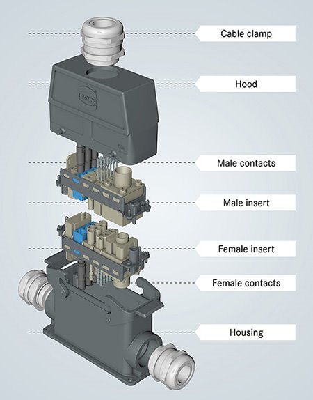 Example of insert, contacts, and housing of a connector.
Source: What Constitutes a Heavy-Duty Connector and Where Are They Used for Industrial Connectivity
Contact termination styles
There are a many different contact connection styles. Sizes and termination styles depend on application and requirements. A few of the more common contact termination styles are as follows:
- Crimped contacts - fast and easy but may require specialized tooling to crimp contacts to wire
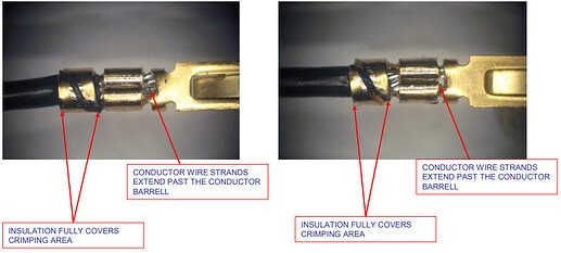 An example of crimping contacts from TechForum:
Source: EDAC 516 Series Crimping Recommendation
- Solder cup - cheap and offer environmental protection and solid electrical connection but take time for soldering
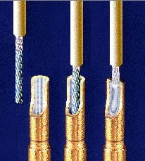 An example of proper solder cup termination
Sourced from: NASA Workmanship Inspection Pictorial Reference
- PC pin – Terminals or single post connectors typically found on circuit boards
 Example of PC pin termination from Amphenol:
Source: Digikey Part Number: 4995-M12A-04PMMP-SF8001-ND
Mounting style
- Free hanging - are the connectors that are placed at the end of a wire or cable, while free hanging connectors can offer more range and flexibility away from the device limited only by cable length they can be damaged more easily or be exposed to more hazards.
- Panel mount – are secured to the exterior of an enclosure or wall. Typically, a hole or a cutout as been made in the enclosure and the connector is place through it. Locking in place by either a nut and threaded neck, using external screws or mounted to the circuit board inside the enclosure. These offer good IP rating protection as the hole the connector made can be sealed by the connector.
- Board mount - Bound mounting connectors is where the primary structural support of the connector is offered by the printed circuit board it is connected to. In addition to the termination of the contacts, there may also be supporting pins or post that need their own space on the circuit board
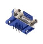 Example of a board mount connector:
Source: Digikey Part Number: L77HDE15SD1CH4FVGA-ND
Dust and moisture prevention
Depending on the operating environment, a connector may be exposed to high or low temperatures, water, dust particles, hazardous chemicals or other environmental conditions that will degrade performance for connector or even cause it to fail completely. A sealed connector is one that has been designed to withstand environmental conditions.
Ingress Protection or IP rating defines to how well a connection is sealed and what type of environmental aspects they can handle. Some examples of the International Electrotechnical Commission (IEC) for Ingress Protection (IP) include:
- IP20 indicates protection from solid objects larger than 12mm
- IP67 indicates protection from water immersion of 1 meter up to 30 minutes
- IP69K indicates resistance to steam and high-pressure water
More on IP ratings can be review here: Subtle Considerations for Connectors in Harsh and Extreme Environments
 A barrel connector showing dust and moisture resistance:
Source: An Overview of IP Ratings and Waterproof Connectors
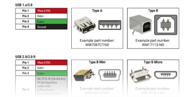
Common Connectors and Pin Outs
A chart of the the most common connectors and terminal pinouts from the DigiKey Innovation Handbook

Connectors – The Basics
Connectors are a prevalent part of almost any electronic project. Understanding the available connectors and the specification considerations that one would need to keep in mind is important throughout the design process.
Wire and Cable
What is the difference between wire and cable? View Answer
While on the surface, wire and cabling may seem very similar and typically used as interchangeable words, they are in fact are two different parts of the interconnect solution:
- Wire is one electrical conductor surrounded by insulation
- Cable is multiple electrical conductors or groups of wires bundled together and surrounded by a layer of outer insulation. Cables have at least 2 or more wires, either bound together by molded insulation or by having individual wires each with their own insulation grouped together and a layer of outer insulation around the group of wire
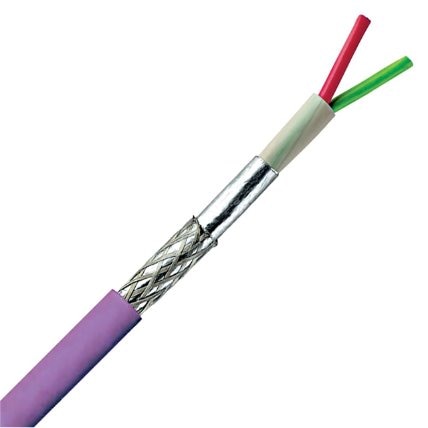 Picture shows a cable contained 2 insulated wires:
Source: Digikey Part Number: 2320-2170820-DS-ND
What is the difference between solid core and stranded wires? View Answer
The conductive channel of a wire typically comes in two different types solid core or stranded
- Solid Core: Like the name suggests, solid core is one solid length of metal, drawn out and then coated with insulation material. Cheaper, thicker, less flexible and bendable but able to carry larger amounts of current
- Stranded: a conductor made up of many smaller uninsulated wires twisted together to form a larger conductor, like the fibers that make up a rope. The larger the strand count the more flexible the wire is. However it can be More expensive per length then a solid core wire
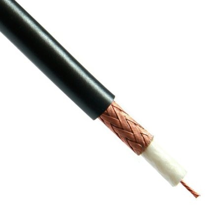 Picture shows a coax cable with solid core wire
Source: Digikey Part Number: BEL1299-100-ND
Wire Material
This is the conductive material that makes up the wire. Typically, this can be aluminum or copper, plated with tin or in some cases silver to improve solderability or heat resistance.
Gauge (size)
The cross-sectional number of dies a wire has been drawn through to achieve a given diameter of wire. The United States wire size is measured by the American Wire Gauge (AWG) the higher the gauge number the smaller the wire diameter. For larger wires, circular mils are used. MCM sizes, also called kcmils (kilo-circular mils), are for even larger cables. One MCM is equivalent to 1,000 circular mils.
AWG: In the American Wire Gauge system, 36 AWG wire has a 0.0050-inch diameter. A 1000 (4/0) wire, has a .4600-inch diameter. There are also 39 gauge sizes in between. It is designed so that the wire area approximately doubles for every three steps on the gauge scale.
Current ratings for wire and cable
The maximum continuous current rating is limited by the size of the wire, or the total number of conductors within the cable, and the outside conditions within the surrounding environment including ambient temperature and airflow.
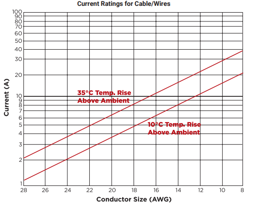 Current Ratings for Conductor Size AWG:
Source: Digikey innovation Handbook
Value Added Services
DigiKey is more than a world class part distribution company. We can also offer and provide a wide range of valued added services, each one to help bring your design from ideas to reality, which includes:
- Wire cutting - a wide breadth of wire and cable product cut to length, including top brands in the industry. We can custom-cut wire and cable of any length, any gauge, and any weight, with no splice, and no minimum including UL certification and supporting European standard wire and cable.
- Ribbon cable – assemblies from the IDC connectors that we stock. Cable assemblies can be made with connectors on both ends or with a connector on one end. They also can have different connectors on each end if the number of conductors are the same.
- Rectangular cable - assemblies with stocking parts.
- FFC - ribbon cable assemblies from the FFC connectors we stock from TE Connectivity. They are listed as a Value-Add item on our web site. Cable assemblies can be made as Solder Tab to Solder Tab, Receptacle Housing to Solder Tab, or Receptacle Housing to Receptacle Housing.
- Precrimp – crimped contacts onto wire.

Wire & cable cutting services
DigiKey offers a wide breadth of wire and cable product cut to length by foot or meter including top brands in the industry. We can custom-cut wire and cable of any length, any gauge, and any weight, with no splice and no minimum.
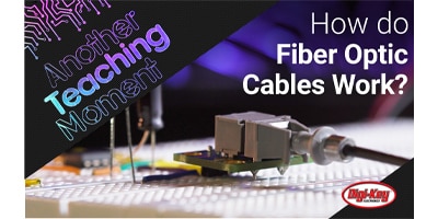
How do Fiber Optic Cables Work – ATM | DigiKey
Fiber optic cables allow signals to travel between nodes at high speeds with low signal loss. In many cases, it is far superior to its physical wire counterpart. Fiber Optic transmitters turn electrical signals into light pulses carried over the cable and later converted back to electrical signals by the receiver.
Crimping Tools
Crimping tools are specialized hand tools or presses that are designed to fold and press the metal contacts of a connector around the conducting wire forming a strong mechanical connection between the contact and wire.
Some crimp tools can perform many different functions of the crimping process such as wire cutting and removing the wire insulation and are able to work with a wide range of wire gauges or sizes.
Can you crimp without a crimping tool? View Answer
Crimping tools are useful to ensure that a clean, reliable crimp is made on the contact around the wire these are much more stable and repeatable then using pilers to fold the contact around the wire. While it is possible to use pilers to crimp contacts onto wire this is not the recommended practice. It is not a reliable method to bond to the contact to the wire, the connector may become damaged (or not fit in the housing) and it will likely take more time to secure the contact.
Manual Crimpers
Hand tooling (also known as manual crimping) is as the name says are hand tools used for crimping contacts on to a wire. These tools can be spring, or ratchet assisted but the main force applied is by the user hand and grip. Typically, these are useful for individual contacts for field repair, or small-scale production with loose piece contacts as everything including placing the wire and contacts to be crimp needs to be done by hand.
Automated Crimpers
Power tools and presses are powered from an external source, electrical or in some cases air powered and are designed to crimp larger volumes. Due to the greater complexity these tools can cost significantly more.
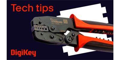
How to Strip and Crimp Wires Easily | DigiKey Standard
DigiKey has answered the call and delivered its DigiKey Standard line of efficient and cost-effective wire stripping and connector crimping ratcheting hand tools. The DKS-STRIPPER6MM2 or Stripper 6, allows the user to set insulation depth to prevent conductor damage and wire length for consistent cuts.
Electrical Specifications
Electrical properties must also be considered when choosing the proper interconnect for an application.
- Wire and Cabling has a certain resistance, typically expressed in ohms per 1000 feet or meters. Although manufacturers work to reduce resistance, there will be some power loss in the form of heat dissipation.
- Connector power rating is the amount of power that can be safely dissipated across both sides of a connector.
How much current can I put through my interconnect (connector, cable, or wire)? View Answer
The rated current (also called the current carrying capacity) is the maximum amount of electrical current the interconnect (connector, cable, or wire) can pass safely. As more electrical power is passed through the interconnect, power is lost as heat due to the small but cumulative resistances of the conducting materials. Going beyond the rated current, can cause melting, sparking, and dangerous failures.
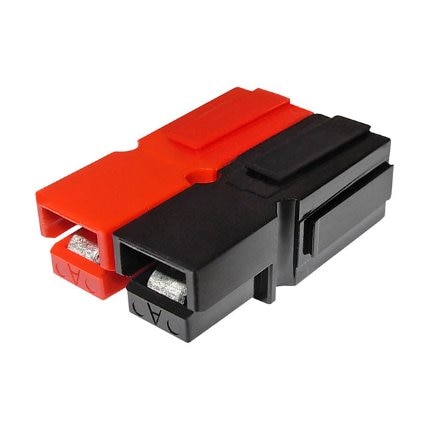 Photo shows a compact connector that can handle 55 amps per pole.
Source: Digikey Part Number: 2243-ASMPP30-1X2-RK-ND
How much voltage can I put across my interconnect (connector, cable, or wire)? View Answer
The rated voltage (also called the working voltage) is the maximum amount of voltage differential a component (or piece of interconnect) can handle. When you look at a wire and a connector together, the combination is only as strong as its weakest link. For a connector factors include the insulation material, spacing between the electrical contacts and environmental conditions. Exceeding this rating may cause the electrical insulation to fail resulting in arcing, damaging the circuit board, or even causing a fire. There are three different values of a connector voltage rating:
- Breakdown Voltage: The product no longer works beyond this voltage. It is also called the Failure Voltage.
- Dielectric Withstand Voltage: 75% of the Breakdown Voltage. It is the non-destructive voltage that the product should be used at. It is also called the Withstand Voltage or Test Voltage.
- Rating Voltage (1/3 of DWV): The maximum continuous voltage that the product should be used at. It is also called the Working Voltage or Operation Voltage.
For questions and more on these, visit the Tech Forum: Difference between the Breakdown Voltage, Dielectric Withstand Voltage and Rating Voltage
What does shielding my interconnect (connector, cable, or wire) do for me? View Answer
Electromagnetic interference (EMI) is noise inherent when you're running multiple power or data signals in a system. EMI effects can be amplified as the power of the signals are increased, or the space between the interconnect is reduced. Shielded interconnect can impact signal integrity and make the difference between passing or failing compliance testing.
 Photo shows a shielded connector.
Source: Digikey Part Number: WM20205-ND
Military and Aerospace Grade Connectors
Mil-Spec (short for military specification) connectors and accessories that meet standards set by the U.S. Department of Defense for environmental protection and interchangeable standardizations of equipment. As the name suggests, these standards were originally developed for military applications such as use in aerospace, but the ability to operate reliably in harsh environments, ability to be customized means that Mil-spec connectors were quickly adopted by industrial, automotive, high-frequency computing and telecommunications applications far outside the original military equipment originally designed for. Today most Mil-spec connector manufactures offer a wide range of circular connector product lines for civilian markets.
What are the common military standards in use today? View Answer
The basis for specifications of the Electrical and fiber optic connectors used by the US Department of Defense today were originally developed in the 1930s but have evolved into a range of applications and markets.
- MIL-DTL-38999
- MIL-DTL-26482
- MIL-DTL-5015
COTS (Commercial off-the-shelf)
Commercial-off-the-shelf (COTS) products are ready-made and commonly available parts or solutions that are offered by the manufacturer. As the manufacturer controls the design, manufacturing, and production, they are not directly compliant with mil-spec qualifications.
Aerospace
Aerospace applications are one of the most demanding environments electrical connectors can find themselves in. Extreme hot and cold temperature ranges, pressure differentials, constant vibrations, and high-power demands with the need for consistent and reliable data links require any connector to meet the highest specifications. Circular connectors meeting various mil-spec qualifications are commonly found on aerospace applications.
Hermetic connectors offer airtight protection across pressurized bulkheads such as passenger cabins or airborne sensor packages.


 Source:


 中国
中国