制造商零件编号 CF14JT220R
RES 220 OHM 5% 1/4W AXIAL
Stackpole Electronics Inc
License: See Original Project Raspberry Pi SBC
Courtesy of All About Circuits
Intro
In the previous project for Build Raspberry Pi Controllers, you learned how to construct a programmable LED flasher. To start the LED flashing cycle, you must press a tactile pushbutton switch. The tactile pushbutton switch is a manual method for providing an input control signal, which the RPi will process and respond to, but you can achieve an automatic approach to control using a sensor. Photocells or light dependent resistors (LDRs) are often used for turning lights on at night. A typical night light has a photocell that can detect darkness based on a change in its resistance. When the photocell detects darkness, the light turns on. Applying this same working principle from a typical night light, we can similarly operate a small DC motor. In this project, you will be building an object detection DC motor controller. Figure 1 displays the block diagram for our object detection DC motor controller. The electronic components required for building the object detection DC motor controller are indexed in the Parts List.
Figure 1. To build the object detection DC motor controller, you will need the shown electronics and the embedded hardware.
Project Parts List
Light Detection and the Photocell
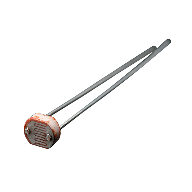
A photocell is a light sensitive resistor. Another term used in textbooks or magazines for electronics hobbyists is a light dependent resistor, or LDR. If you have never seen a photocell, Figure 2 shows the electrical symbol, as well as a component view of a LDR.
Figure 2. The electrical symbol and component view of a photocell
Changing resistance is the photocell's electrical response to light. Its resistance decreases down to a few hundred ohms as it receives more light on its sensitive surface. The photocell resistance is in the megaohms in the dark. You can conduct an experiment to measure how the photocell's resistance changes based on light. First, set a DMM (digital multimeter) to read ohms. Adjust the ohmmeter scale to the setting for 20 kilo ohm. Connect the DMM's negative and positive test leads across the photocell, as seen in Figure 3. The reading shown on the ohmmeter will be in a few thousand ohms.
Figure 3. The author’s ohmmeter reads a value of 3.11Kilo-ohms. Note: Resistance values vary based on the ambient light that the photocell receives.
Next, adjust the scale to the highest setting for megaohms. You will see a resistance value in a few millions of ohms, as seen in Figure 4, if you place your hand over the photocell.
Figure 4. The author's ohmmeter displays a value of 1.587 megaohms.
Make a collimator, which is a device that narrows light, for the best results. First, cut the barrel of an ink pen and paint the inside of it black. Place the collimator over the photocell once dried. This reduces ambient (outside) light from disturbing the ohmmeter’s resistance reading. I made a collimator with the "finger grip" of a pen as shown in Figure 5. The resistance measurement obtained in Figure 4 is based on a homebrew "finger grip" collimator. These minimum and maximum photocell resistance values allow us to, on a solderless breadboard, wire a simple light sensor switch to the RPi.
Figure 5. The author's homebrew collimator was constructed from a pen’s finger grip.
Build a Basic Light Sensor Switch
We will use the photocell, as well as a pull-up resistor, and make a simple light sensor switch. Figure 6 displays a basic circuit schematic diagram of the light sensor switch that is wired to an RPi GPIO pin. The volume of photocell resistance is proportional to the voltage drop. Placing an object or your hand over the photocell, for example, will provide an approximate +3,3VDC voltage drop across the LDR. When removing your hand or the object, it reduces the photocell's resistance. This provides a proportional small voltage drop across it. The RPi GPIO pin will read them. The absence and presence of the light will be read, by the Python code, as either +3.3VDC or 0VDC. This means the electrical behavior of an ordinary tactile pushbutton and a digital switch will be emulated by a simple light sensor circuit. The next phase of the project involves building and testing a DC motor operated by a transistor.
Figure 6. This simple light sensor switch is constructed using a photocell and a pull-up resistor. Note: The pull-up resistor is a programmed electrical component, and it uses a single line of Python code.
Build the Transistor Motor Driver Circuit
The next phase of the project build involves wiring an electronic circuit that operates a small DC motor. A single bipolar junction transistor (BJT), along with an appropriate amplification factor (Beta), can operate or drive a small DC motor. You can easily construct a transistor DC motor driver, as shown in Figure 7, by building the circuit on a solderless breadboard. As additional wiring reference material, as shown in Figure 8, I've also included the electronic circuit schematic diagram. Once the circuit has been built on the solderless breadboard, pressing the tactile pushbutton switch will turn on the small DC motor, which is wired to the transistor's collector lead. Remove the battery pack from the circuit, if the DC motor doesn’t spin, and recheck your wiring and component orientation of the 1N4001 rectifier diode, as well as the 2N2222 NPN transistor. After you have corrected the wiring errors, reconnect the battery pack and test the circuit again. Congratulations, you’ve built a functional transistor motor driver circuit! Now, let's see how the DC motor driver circuit works and review basic transistor theory.
Figure 7. A wiring diagram for the transistor motor driver solderless breadboard
Figure 8. A DC motor driver’s electronic circuit schematic diagram
Basic Transistor Theory
Because of the electrical source current, which flows from the +6VDC battery pack through the collector-emitter leads to ground), the transistor is able to operate the DC motor. In series between the collector lead and the +6VDC battery pack is the DC motor winding. The electrical current from the +6VDC battery pack flows through the dc motor winding, which allows it to rotate. In order for the electrical current to flow through the collector-emitter leads, as well as the DC motor winding, the transistor must be on. To turn on a transistor, you must use an electronic circuit operation technique called forward biasing. To forward bias a transistor, you must apply an input voltage to the base-emitter junction that is greater than 0.7V (700 mV). Also, based on the semiconductor component type, the transistor must be properly wired. BJT component types include a PNP or NPN pin configuration. One NPN component is a 2N2222 transistor.
The collector and emitter leads are negative (N-material), and the base is positive (P-Material). Figure 9 displays the pin configuration and package type for the 2N2222 NPN transistor. As displayed in Figure 8, the base attaches to the +6VDC battery pack positive-red wire through a tactile pushbutton switch, as well as a 220 ohm series limiting resistor, with the emitter wired to ground (the black wire). A 220 ohm resistor attaches to the transistor's base and reduces the full battery current and prevents heat from damaging it. The 220 ohm resistor is a nice resistance value, which allows a sufficient amount of base current to flow, in order for the transistor to turn on properly. Also, the 1N4001 diode stops back peak reverse current from the DC motor winding from damaging the transistor when it turns off. To learn more about this semiconductor device, read AAC's article on Bipolar Junction Transistors for additional electrical theory information. Lastly, let’s move on to the final hardware build of the project.
Figure 9. The electronic symbol, as well as the component package type for the 2N2222 NPN transistor, are pictured above.
Final Hardware Build
Now that the transistor motor driver circuit works properly, we can complete the final hardware build. The final electrical step for the object detection/DC motor controller is wiring the driver circuit to the Raspberry Pi. In the LED flasher project, we utilized the Adafruit Pi cobbler to connect the opto-isolator and support circuit components to the appropriate RPi's GPIO pins. The Pi Cobbler is convenient because of all the RPi GPIO pins accessible on the solderless breadboard for electrical wiring to electronic interfacing circuits. Thus, the same circuit wire assembly technique will be employed in this project as well. Figure 10 displays the solderless breadboard wiring for the object detection DC motor controller. Again, we’ve provided the electronic circuit schematic diagram displayed in Figure 11 as an additional wiring resource.
Figure 10. The object detection DC motor controller wiring diagram has been assembled on a solderless breadboard. Notice the absence of the tactile pushbutton switch, as well as the +6VDC battery pack and the new placement location of the solderless breadboard’s electronic components.
Figure 11. The object detection DC motor controller’s electronic circuit schematic
An example of the object detection DC motor controller, which I provided by way of my prototype unit, is shown next. Using an old Erector set metal base, along with a Meccano DC motor, I attached it for my prototype build. The video clip below shows how the controller works. The final step in constructing this object detection DC motor controller operational is adding the Python code.
Figure 12. The final build of the object detection DC motor controller. The 2N2222 transistor has enough Beta for it to properly drive the Meccano erector motor without overheating it.
The Object Detection Python Code
The Python code shown below was reused from the LED flasher project. The variable names were changed, and now they reflect the physical components wired to the RPi. The code places an object over the photocell and turns the DC motor on. A second object over the sensor will turn the DC motor off. As discussed earlier, the pull-up resistor is a component that has been programmed using the following line of Python code:
GPIO.setup(photocell_pin, GPIO.IN, pull_up_down = GPIO.PUD_UP)
Once you’ve opened the nano editor with the Linux command ~sudo nano object detection.py, the entire Python program can be typed onto the LXTerminal. Also, the Python program can save to your RPi's SD card if you click the code button below.
                   # ***********Object Detection code******************
#
# inspired by Simon Monk, Raspberry Pi Cookbook, 2013
#
# modified by Don Wilcher Dec 18, 2015
#
# Placing a object over the photocell will turn on the dc motor.
# Placing an object over the photocell a 2nd time turns off the motor.

# Add libraries to python script

import RPi.GPIO as GPIO
import time

# Include BCM I/O pins into python script and define pin numbers

GPIO.setmode(GPIO.BCM)
photocell_pin = 4
motor_pin = 18

# Create photocell pin as an active low switch (use RPi internal pullup resistor)
# and define motor pin as an output.

GPIO.setup(photocell_pin, GPIO.IN, pull_up_down = GPIO.PUD_UP)
GPIO.setup(motor_pin, GPIO.OUT)

# Define and set (initialize) the motor output state as False and the old input event as True

motor_state = False
old_input_event = True

# pbswitch event monitoring loop: check pbswitch_pin and toggle dc motor  output based on input events
# being True or False
while True:
    new_input_event = GPIO.input(photocell_pin)
    if new_input_event == False and old_input_event == True:
        motor_state = not motor_state
    old_input_event = new_input_event
    GPIO.output(motor_pin, motor_state)
    time.sleep(0.1)#provides a 100 msec motor actuation on/off time
Once the objection detection Python code has been into the LX Terminal, after the prompt on the screen, type the Linux command ~sudo python object_detection.py. Place an object over the photocell. Then the DC motor should be spinning. By placing the same object over the LDR, the motor will turn off. Congratulations! You have a completed operational object detection DC motor controller. You can apply this device as a non-contact start switch for a conveyor system. Instead of starting the conveyor with a standard pushbutton, you can use a basic hand motion. Experiment with other applications for your object detection DC motor controller, and be sure to record them in a lab notebook. Next time, we'll build an event counter using the RPi, as well as with litteBits modules.
Download the code for this project here.