Bebop: A Quick Facial Recognition Robot for Maker Faire Rome
2023-11-10 | By Jorvon Moss
License: General Public License
Bebop is a facial recognition robot I built to showcase at Maker Faire Rome. I wanted to create a quick wearable with decent functions, so I built a pan-tilt mechanism-based facial recognition robot using the Person Sensor. I've made facial recognition robots before, but this was the newest, fastest, and easiest way to put one together. What makes this robot special are the ball joints. With ball joints in almost every mechanism, the robot is poseable, which makes wearing Bebop look cooler.
Parts
- 1x Pan and tilt - 1568-1717-ND
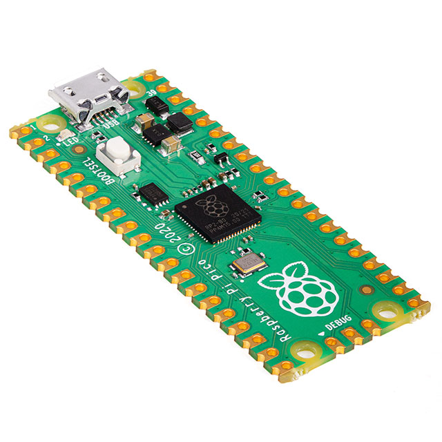
- 1x Pi Pico - 2648-SC0915CT-ND
- 1x Large Servo - 1738-1456-ND
- 1x NeoPixel - 1528-1102-ND
- 1x Battery - 1528-1836-ND
- 1x Person Sensor - 1568-SEN-21231-ND
STLs for the 3D-printed parts can be found here: https://www.thingiverse.com/thing:6295476
Circuit
Tilt Servo, Pin 39 Power, Pin 28 ground, Gpio pin 2 signal
Pan Servo, Pin 40 power, Pin 3 ground, Gpio pin 1 signal
Person Sensor. Signal pin 1 Gpio pin 4, signal pin 2 Gpio pin 5, Pin 36 power, pin 38 ground
Optional LED
LED, Pin 36 power, Pin 33 Ground. signal pin 24 Gpio pin 18
The code for this project can be downloaded here:
Assembly
I attached the person sensor print to the tilt mechanism. The tilt mechanism is used to make the eye move up and down. You can glue the mechanism to the inside of the head, leaving enough room for it to move up and down. The person sensor should be placed outside the head so that it can see people. The entire circuit, including the battery, can be fitted inside the head. If possible, a switch or button should be placed outside the head to turn the device on and off.
I recommend having some type of strong adhesive for the 3D printed pieces in this build because I was in such a rush, I didn't design it to use screws, unlike most of my other designs.
I recommend printing out the base, body, and leg ball joints first. You're going to want to glue the screw to the body on all four sides. This is a ball joint, so once the screw is attached to the body, you should be easily able to test the strength by attaching the ball and then the screw as seen in the picture above. Once that is completed you may print out the shin joints.
To make the full leg, glue the small attachment onto the end of the ball joint. Then, use a 3 mm or 4 mm screw to attach the shin joint. I also made a leg attachment if you want to make the legs longer.
I designed a foot for this build, but it's not really necessary. It's mostly for show, but if you want to use it, I recommend printing it out and then gluing it to the bottom of the little portion of the leg.
The torso is a simple assembly. It is just a large ball joint, so you should print the large screw piece and the large servo ball joint next. I had to cut the servo ball joint in half because it would not fit with the servo attachment.
I recommend putting the ball joint inside the base of the body and screwing it in there tightly before using the adhesive to glue the top of the ball joint onto the body.
The final product should resemble the image provided below, but with all of the elements combined.
I recommend printing out Bebop’s skull piece next. This is where most of the circuitry goes. I put a lot of circuitry on top of this piece, including the circuit board, battery, and pan mechanism. On the bottom, you can see there is a hole for the servo horn. You will insert the round servo horn into this small hole and screw it in or use adhesive to secure it in place. This allows the servo to turn the head correctly.
In my opinion, the head is the final piece that you should print. It is the complete enclosure for the system. Once you have printed it, you will have all of the circuitry inside and everything working correctly. Simply print it out, and there are two small holes in the back that you can use to add some screws. I recommend using wood screws to keep it in place.
If you add the LED and you haven’t put the top on just yet, it should look something like this:
This is what it should kind of look like when it's fully assembled.
I have a unique way of characterizing the eye by dividing it into three parts: first, a person sensor; second, an eyelid covering the LED; and third, a final covering that I printed in white and painted the upper area black. This gives the eye a cool feature.
This build was originally made with my friend Becky https://www.youtube.com/watch?v=lO3xgYEBuKg who made this really cool carrying bag, but I couldn't take it with me to my last event so I used a GoPro attachment to attach it to the strap of my backpack.
You can print a piece to add to the bottom of the robot, and the attachment is the same one you use for any GoPro camera. The ball joints allow you to move it around your body to make it look like it's really holding on to you, and you can get a cool picture like this.

Have questions or comments? Continue the conversation on TechForum, DigiKey's online community and technical resource.
Visit TechForum


 中国
中国