Another Ambassador Moment: DIY Simple Data Acquisition System for EV
2022-01-07 | By Robby Huang
License: Attribution Non-Commercial No Derivatives
Figure 1: Block diagram of the data acquisition (DAQ) associated with the electric vehicle (EV).
System Description
The DAQ system handles the communication of data from electrical systems and sensors to the driver and the team. This year’s system is designed to transfer almost all data to an ATmega2560 based PCB and then to the dashboard via Bluetooth. Only the Lord Sensor (see Figure 1) will be collected through the Xavier and then sent to the board. The DAQ will be using many powerful sensors so the main objective is to organize and parse the data in an efficient manner. The two main sensors, RTK GPS & Lord Sensor, each have their own built-in GUI and app, so they can be used for testing and mapping data before being placed on the car. When the two sensors are placed on the car itself, the RTK will be sending data directly to the DAQ via a specialized program written with C libraries to collect the data in real-time. Lord Sensor data will be collected through a program written that references a ROS Library and sent to the DAQ to be parsed and transmitted to the dashboard via Bluetooth. Using an ATmega2560 with a dual UART connection was used to help minimize the size and efficiency of the transmitted data. Because Bluetooth is being used as the main communication between the DAQ and the Dashboard, there is a limit to how much of the data can be sent in packets. So, the data will be parsed in an understandable and effective manner. The BMS will communicate with DAQ through an I2C connection.
Terminology
DAQ- Data Acquisition: Handles communication of data from electrical systems and sensors to driver and team.
Server: A program/script that is constantly running on the internet, listening to requests from users, and taking relevant actions.
BlueTooth: Wireless technology standard for exchanging data over short distances from fixed and mobile devices.
BLE: Bluetooth Low Energy is a wireless personal area network technology designed and marketed by the Bluetooth Special Interest Group aimed at novel applications in the healthcare, fitness, beacons, security, and home entertainment industries.
Database: A reliable place to store important data. It is an organized collection of structured information, or data, typically stored electronically in a computer system.
Battery Management System (BMS): Electrical component that controls the distribution of electricity to all major components of the car.
Motor Controller (MC): Electrical PCB that regulates and controls the main motor Lord Sensor IMU (Inertial Measurement Unit): Specialized sensor that measures multiple types of data (position, heading, acceleration etc.)
RTK Rover Module: Component on the car that connects to the base station to receive data (Longitude, Latitude, Altitude, Speed, Course etc.)
RTK Base: Large system that receives data from the rover module and establishes the correction input
Joulemeter: Electrical component that measures the energy being used by the motor controller.
Lord Sensor: The 3DM-GX5-45 all-in-one navigation solution features a high-performance, integrated multi-constellation GNSS receiver utilizing the GPS, GLONASS, BeiDou, and Galileo satellite constellations.
Product Highlights:
- High-performance integrated multi-constellation GNSS receiver and advanced MEMS sensor technology provide direct inertial measurements, and computed position, velocity, and attitude outputs in a small package.
- Triaxial accelerometer, gyroscope, magnetometer, temperature sensors, and a pressure altimeter achieve the optimal combination of measurement qualities.
- Dual on-board processors run a new Auto-Adaptive Extended Kalman Filter (EKF) for outstanding dynamic position, velocity, and attitude estimates.
Background Research
The DAQ collects, reads, and sends various data for multiple sensors located throughout the vehicle. Data from various sensors is communicated to the ATMega2560 (Arduino Mega microcontroller) via various communication protocols like I2C and UART. The data then gets transmitted to a BlueTooth module (Adafruit Feather 32u4 Bluefruit LE) which sends the data in packets to the dashboard.
Design Requirements
- Communicate with multiple sensors and collect different types of data for testing purposes
- Data must be parsed (organized and sent in specific packets) to transmit in a readable format to the drive and testing team
- Final design must effectively send position data to dashboard and server
- DAQ PCB sends most data to Arduino MEGA
- Sensors must be set and programmed to be used outside of the car for tasks (track map reading, data simulation, and drive tests)
- Computers reading data from sensors need to have the proper drivers and programs installed to read the data correctly
- Must be compatible and send data to Jetson & Xavier GPU
See Figure 1 for the overall system diagram
Design Overview
One of the main challenges with creating a DAQ is the various communication protocols and the dependencies that come with various sensors. For example, with the Joulemeter design, the wattmeter does not come with an easy way to connect to the DAQ, so we have to hack our own. Thus, keeping the DAQ communication protocols as uniform as possible is a helpful way to guarantee a working DAQ system with minimal to no faults.
Additionally, as we realize debugging is inevitable with the DAQ, we added extra headers to the I/O ports of the ATMega2560 just in case we find a different way to communicate with a specific sensor or if the team wants data using a different sensor. Overall, our main goal with the design and layout of the DAQ is to allow for flexibility in debugging and hacking.
Component Selection
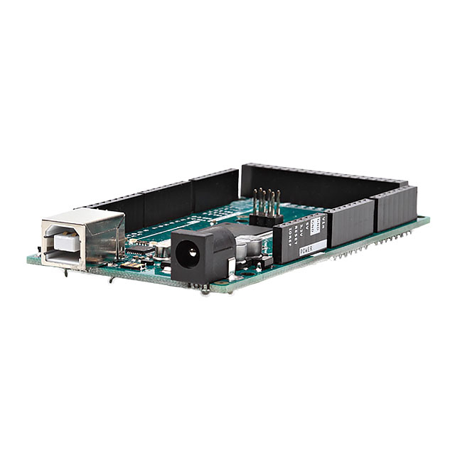
Arduino Mega: At first, we were going to use an ATMega328p (the microcontroller used in Arduino). However, we realized with such a microcontroller we could only have one UART connection which would have had to be used with the GPS RTK since UART is its only communication protocol. The Jetson/Xavier, for example, is much easier to connect to via UART rather than connecting over I2C. Additionally, converting more connections to UART would make it easy for us to debug and decrease the amount of code we would have to write. The increasing need for UART communication protocols led me to switch microcontrollers to one that accepts 4 UART connections (Arduino Mega).
REACH M+/RS RTK GPS: We were able to get it for free via EMLID Sponsorship through Event 38, a store that sells various devices for unmanned rovers. The Reach modules are able to communicate with the Arduino, can parse data to flexible data formats, and are accurate to the millimeter.
LORD Sensor: We were able to get this for free through sponsorship from MicroStrain. The LORD sensor is multifunctional as it has both a GPS and an IMU. From this, we are able to collect Heading, Acceleration, Velocity, Yaw, Grade, and many other parameters.
LORD Sensor Data sheet
Joulemeter Components: The purchased watt meter was only ~$15 and is reliable, hence a very worthwhile purchase.
Schematic
Figure 2: Top-level schematic for DAQ.
Figure 3: Top-level schematic for DAQ MCU.
Figure 4: Input/output part of DAQ schematic.
Load Cases
- The antenna for the GPS RTK is supposed to have an unobstructed path to the sky to collect the most accurate data
- DAQ as a whole system is rated for a maximum of a 5 V input
- Potentiometers and IR sensors must also only input a maximum of 5 V as an analog input so that the microcontroller does not malfunction or get damaged
Results & Optimization
We are currently testing the accuracy of the GPS RTK to ensure that it is more accurate than last year's GPS and is sufficient for autonomy, motion planning, and localization. Currently, we have found it easiest to connect the RTK module just to a public base station in Arizona, as it does not require setting up or connecting our base station to the NTRIP communication flow. A way to optimize the accuracy would be figuring out how to communicate with our Reach M+ base station.

Have questions or comments? Continue the conversation on TechForum, DigiKey's online community and technical resource.
Visit TechForum









 中国
中国