


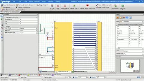
This section explains the property window and the object window as useful functions. The property of a selected object can be confirmed and changed in a moment on the property window an the attributes of multiple objects can be changed at once.
GRID is the reference lines at the constant interval. It can easily be changed at the bottom of the screen. GUIDE is the intervals to snap the cursor when the crusor gets close. With the arrow keys you can move your cursor at a constant interval.
Use your mouse wheel to zoom your screen in and out. You can also move your screen by clicking and holding the right button and dragging your mouse till you adjust your view.
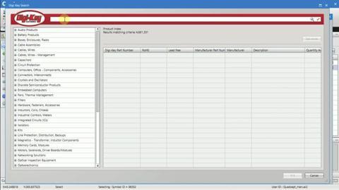
Quadcept is now cooperating with DigiKey, one of the largest online component distributor with direct interface. User has direct access up to 4 million components on DigiKey from Quadcept and select components by keyword search or filtering.
Thank you for your interest in Quadcept. Let's learn about the basic operations of Quadcept.
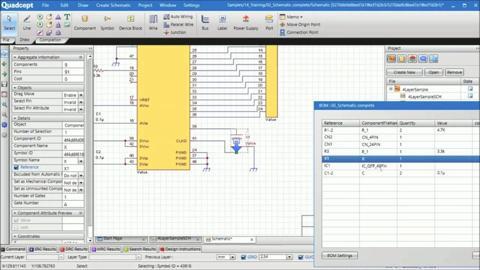
Once your schematic is completed you can export a BOM. When clicking on a Component on the BOM window it will show you where that component is located at on your schematic. Your BOM will be exported in CSV Format.
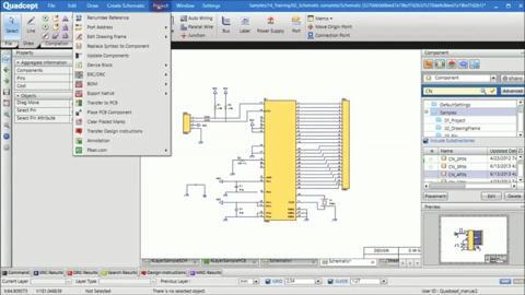
Using these easy steps you can create a schematic easily. After creating a schematic, check if there is no problem with the connection between components and the layout of a schematic. There are many verification items in Quadcept.
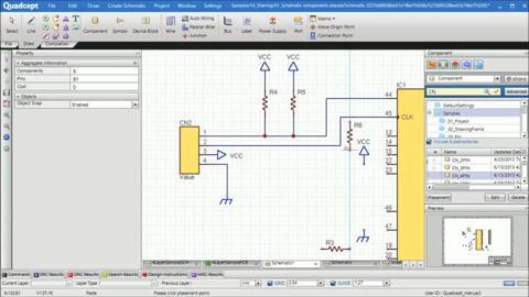
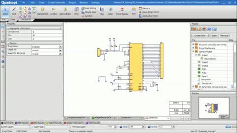
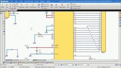
Now that all your components are placed, it's time to connect them using wires. You have multiple ways of wiring that are manual, auto and parallel wiring. Clicking and dragging from a pin allows to start a wire.
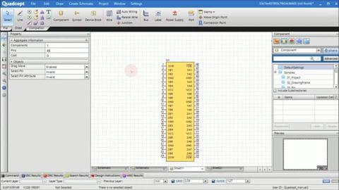
Now let's place components . Using the component window you can select and place components.
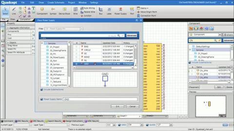
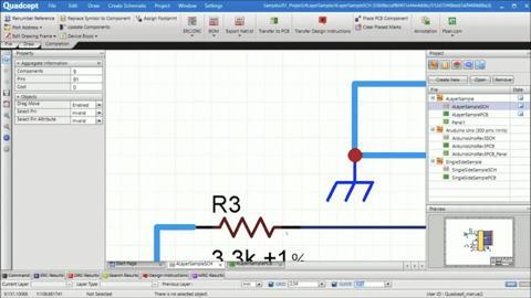
A power and ground nets can be easily placed by just selecting a shape and enter a name for it and finally place it in your desired location.
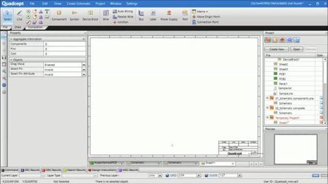
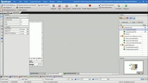
Now let's create a new project. When creating a new project, it will be created on a project window. A new schematic sheet will automatically appear on the central design area. If you need multiple schematic sheets, add them to the project like this.
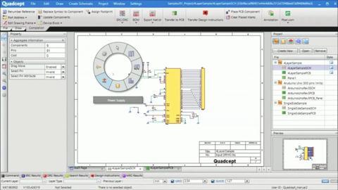
In this section, we will introduce schematic design flow. A schematic is created by placing components and then connecting them with wires.
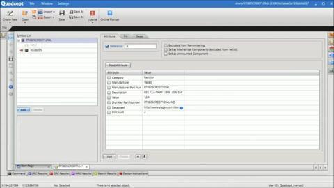
Quadcept offers a component library called Share. If you cannot find a component you wish to use, you can edit or create any component and use it. You can always edit and save any component.
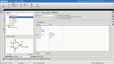
You can manage your components like actual ones. You can use multiple shapes if you'd lke and it is possible to register gates as well as multiple Footprints. It is also possible to set alternate shapes of a symbol in advance.
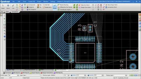
And then, you want to connect your components using Routes. To connect these routes it is the same as wire, just click on the location where you want to bend the Trace and continue till you connect it.
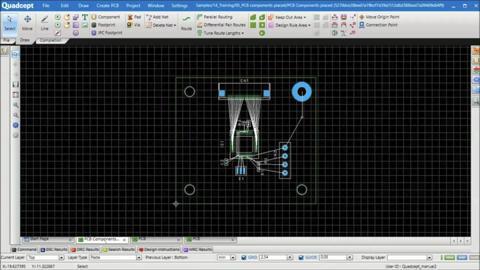
Next, let's place components . Using the component window you can select and place components. By selecting a component from your schematic you can place that component to your layout design.
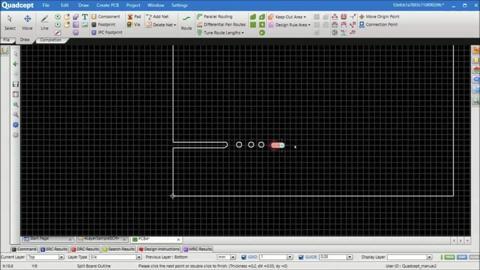
Creating a board slit are easy, all you have to do is enter its width. You can also create a Keep Out Area easily by entering offset values.
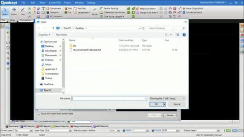
Now, draw a board outline here. A DXF file is imported as a board outline here, but it is possible to draw it using lines. In Quadcept, draw your outline on the board layer labeled OTHER.
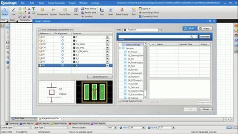
If your schematic was created using Quadcept and all components have a registered component, then it is possible to transfer the connection information through PCB Transfer function/button.
In this section we will introduce PCB Design flow. How to create patterns on a printed board based on the connection information and components created in a schematic.


 中国
中国