How To Calculate and Use RC Time Constants
2024-04-24 | By Maker.io Staff
One of the first things we learn in Electrical Engineering school is about the humble resistor-capacitor (RC) network. Equipped with the right knowledge, this simple combination of two components can achieve many things from controlling a circuit’s timing to filtering out high-frequency noise components. This article answers the questions of what is an RC time constant, and how you can use it in your circuit designs.

An RC Network
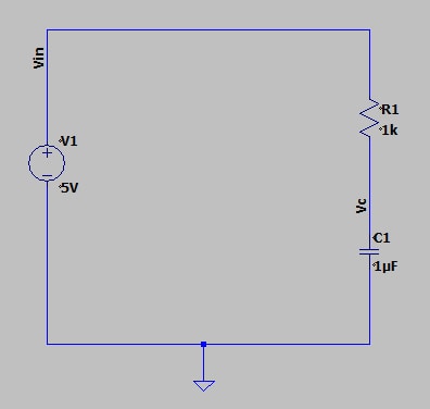
Before we can understand what a time constant is, we first need to understand the basic operation of an RC network. Consider a simple RC network consisting of a 1kΩ resistor and 1uF capacitor in series with a 5V source.
 This schematic shows a simple RC network.
When the circuit is connected at time t0, current will begin flowing from the positive terminal of Vin, through the resistor R1, and into the capacitor C1. This capacitor in this circuit effectively accepts the current flow until the voltage across the capacitor reaches the level of Vin, at which point the circuit will be in equilibrium, and no more charge will flow.
 The blue trace shows the voltage Vc across the capacitor as a function of time. The green trace shows the current through the resistor R1 as a function of time.
However, the voltage across the capacitor does not instantly reach the value of Vin at time t0. Capacitor charging is a physical process and, despite the fact that electrons move at incredible speeds, the capacitor still requires a certain amount of time to charge up. In fact, the amount of time it takes the capacitor to fully charge will be limited by the value of the resistor R1, which effectively is a current limiter in this circuit.
What is an RC Time Constant?
In Electrical Engineering, the time constant of a resistor-capacitor network (i.e., RC Time Constant) is a measure of how much time it takes to charge or discharge the capacitor in the RC network.
Denoted by the symbol tau (τ), the RC time constant is specifically defined as the amount of time it takes an RC circuit to reach approximately 63.2% of its final value. This number comes from the mathematical equations that govern the behavior of capacitors, which charge exponentially and behave as first-order systems. In the same way, it is a characteristic of RC networks that they are considered fully charged after 5 time constants (5τ).
How to Calculate and RC Time Constant
For the purposes of this article, we won’t go through the derivation that leads us to our final answer. But the important thing to know when working with RC networks is that the RC time constant is mathematically described as

In the example of our previous circuit, which would mean that our time constant is calculated as

Given that our final voltage in our previous example is 5V, that would mean that after 1 ms, our capacitor should have charged up to 3.16V, or 63.2% of its final value. And, sure enough, looking back at our plot, we see that after 1 ms, the blue trace indicates a capacitor value of around 3.1V.

DigiKey’s Time Constant Calculator can help you calculate time constants for your electronics projects.
Unintentional RC Time Constants
While RC time constants may seem trivial, they are important because they end up appearing almost everywhere in circuit design, and often unintentionally.
Since the world is non-ideal, conductors (i.e., g wires, traces, interconnects) exhibit parasitic impedances. Based on the geometry and material of a conductor, it exhibits some element of resistance. At the same time, the geometry, material, and layout properties of that same conductor, will also exhibit some capacitive properties. What this means is that, whether or not you intend to design an RC time constant, essentially every circuit in the world has RC behavior.
So, a firm understanding of RC networks and how to calculate RC time constants will be crucial in all designs you do.
An RC Example: Turning on a MOSFET
To better understand the implications of RC time constants, consider the example of turning on an N-channel MOSFET.
The first thing to note is that the turn-on condition for an N-channel MOSFET is that its gate-to-source voltage needs to exceed its threshold voltage as defined by the following equation

The other thing to note is that, due to the construction of a standard MOSFET, the gate of the device is effectively a large capacitor. To limit the current going into the MOSFET, say if it is driven by an MCU pin with limited output capability, standard practice is to use a resistor in series with the MOSFET gate. What that means is that, if you want to turn on the MOSFET, you need to charge an RC network and that behavior is dictated by its time constant.
 This circuit shows an RC network driving a MOSFET.
In this situation, assume our MOSFET threshold voltage is 0.7V. With an input voltage of 5V, that means we need to charge the MOSFET gate capacitance to 14% of its final value, or ~0.22τ to trigger the MOSFET. Assuming a MOSFET input capacitance of 3500pF, and a series resistor of 10Ω, our time constant is

Therefore, it would take roughly 7.7 nanoseconds to trigger the MOSFET into the on-state. This may seem like a tiny amount of time, but when working with digital circuits at the gigahertz range, every second matters.
Summary
RC networks are one of the most standard circuits in the Electrical Engineering world, and they’re also the most ubiquitous. With a strong understanding of what RC time constants are, how to calculate them, and why they’re useful, you can confidently design and understand your next circuit.

Have questions or comments? Continue the conversation on TechForum, DigiKey's online community and technical resource.
Visit TechForum


 中国
中国