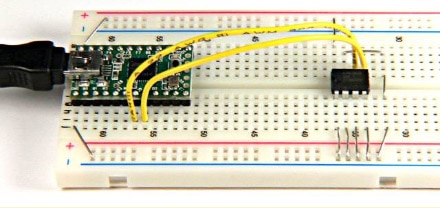
制造商零件编号 DEV-16771
TEENSY 4.1
SparkFun Electronics

This article assumes that you are already familiar with using ADS1115 in other simpler platforms such as Arduino, but you are still confused about how to use ADS1115 in Zephyr. If you are not familiar with ADS1115, please help yourself to Adafruit’s guide. Or if you just want to look at the code to make this possible, here it is.
First, we will start with the devicetree overlay. If you are not familiar with a devicetree, it is a configuration file for the compiler to know what hardware definitions to prepare for you in your C code, so that you can reference them.
&lpi2c1 {
status = "okay";
clock-frequency = <I2C_BITRATE_FAST>;
ADS1115name:ADS1115@48 {
compatible = "ti,ADS1115";
status = "okay";
reg = <0x48>;
label = "ADS1115 addr48 @ i2c1";
#io-channel-cells = <1>;
#address-cells = <1>;
#size-cells = <0>;
};
};
Let’s go through the things you probably would need to change.
Now let’s understand what this devicetree entry is saying. On the first line, the “&” symbol means we are adding to an existing device, if you look at the .dts file of your board, it will reveal that there are most configurations for the same device. On the second line, status = “okay” means that this device is enabled as opposed to status = “disabled.” On line 6, compatible = “ti,ADS1115”; means that it is compatible with this driver. But this driver doesn’t allow you to read from rdy interrupts nor cycle through the different channels of input through the mux; therefore, we will not be using it here. And for the number of channel cells and address cells, it is only 1 instead of 4 because the drivers don’t support it, but we can manually reference each channel without the drivers as we can see later. All the other lines are pretty self-explanatory.
#include <zephyr/kernel.h>
#include <zephyr/device.h>
#include <zephyr/drivers/i2c.h>
#include "ads1x15.h"
#include "ads1115_defs.h"
// i2c adc devices
struct i2c_dt_spec ads_i2c = I2C_DT_SPEC_GET(DT_ALIAS(adcchamberpressure));
int main_thread(void)
{
int ret;
if (!device_is_ready(ads_i2c->bus))
{
printk("the i2c bus for the ADS1115 is not ready\n");
return -1;
}
while (true)
{
// send configuration to ADS1115
ret = ADS1x15_set_config(
ads_i2c,
(ADS1115_REG_CONFIG_MUX_DIFF_0_1 |
ADS1115_REG_CONFIG_OS_SINGLE |
ADS1115_REG_CONFIG_PGA_6_144V |
ADS1115_REG_CONFIG_DR_860SPS |
ADS1115_REG_CONFIG_MODE_CONTIN |
ADS1115_REG_CONFIG_CMODE_TRAD |
ADS1115_REG_CONFIG_CPOL_ACTVLOW |
ADS1115_REG_CONFIG_CLAT_NONLAT |
ADS1115_REG_CONFIG_CQUE_1CONV));
if (ret != 0)
return 1;
// wait for data
k_sleep(K_MSEC(100));
int16_t 16bit_number = ADS1x15_read(ads_i2c);
double voltage = 16bit_number * (6.144 / (32768));
printk("channel 1: %lf", bufferVolts);
}
return 0;
}
K_THREAD_DEFINE(thread_main, 40960, main_thread, NULL, NULL, NULL, 1, 0, 0);
This code demonstrates how to configure and read data from the ADS1115 using the I2C protocol in Zephyr. The main_thread function first checks if the I2C bus is ready, then enters a loop where it configures the ADS1115 and in the while loop reads voltages from ADS1115 continuously.
Within the while loop, we send the configuration to ADS1115 on line 25, which triggers the ADS1115 to start sampling the analog voltage. Here, there is a lot of configurations that we are sending to the ADS1115. Let's go through them one by one:
If you want to alter these configurations, please substitute each one according to the macros defined in this file.
And after we set the configuration, we then read the data from ADS1115 and scale it from the range of -32768 to 32768 to the range of -6.144 to 6.144. This will change a bit if you choose a different configuration for the Programmable Gain Amplifier in the configurations. With the correct voltage value now parsed, we print it out and finish our task of getting voltage from the ADS1115 ADC into Zephyr and ready to be used in your program.
But before we wrap up, we did use 2 unexplained functions (ADS1x15_set_config(ads_i2c, config_bitmask) and ADS1x15_read(ads_i2c)). So, let’s also look into what is going on in these functions.
static int ADS1x15_set_config(const struct i2c_dt_spec *ads_i2c, uint16_t config_bitmask)
{
int err;
uint8_t sendConfigBuff[3];
sendConfigBuff[0] = ADS1115_REG_POINTER_CONFIG;
*((int16_t *)&sendConfigBuff[1]) = sys_cpu_to_be16(config_bitmask);
err = i2c_write_dt(ads_i2c, sendConfigBuff, 3);
if (err != 0)
{
printk("write i2c error\n");
return -1;
}
return 0;
}
Here, we send this configuration to ADS1115 by first reordering the bytes to be in big-endian as my microcontroller on Teensy 4.1 is in little-endian. This is done with the sys_cpu_to_be16 function. Then, we can write these bits to the ADS1115 with the i2c_write_dt function, completing the task.
static int16_t ADS1x15_read(const struct i2c_dt_spec *ads_i2c)
{
int err;
static const uint8_t sendDataReqBuff = ADS1115_REG_POINTER_CONVERT;
err = i2c_write_dt(ads_i2c, &sendDataReqBuff, 1);
uint8_t rx_bytes[2];
err = i2c_read_dt(ads_i2c, rx_bytes, 2);
int16_t value = ((rx_bytes[0] << 8) | rx_bytes[1]);
return value;
}
Here, we get data back from ADS1115 by telling the address of the data that we want to retrieve. In this case, we stored this in the ADS1115_REG_POINTER_CONVERT macro. We write this request to the ADS1115 with i2c_write_dt just like when we set the configuration. We follow this request to the operating system with a request to read from the I2C bus into the byte array of rx_bytes with the call i2c_read_dt(ads_i2c, rx_bytes, 2).
Integrating the ADS1115 into a Zephyr-based project involves several crucial steps, from configuring the devicetree overlay to writing the appropriate C code for I2C communication. This guide walked through setting up the devicetree for the ADS1115 and writing C code to configure and read data from the ADC. Understanding the specific configuration settings for the ADS1115, such as the multiplexer, gain, and data rate, is essential for tailoring the ADC to your application's needs. Hopefully, you find this article helpful, you can now leverage the ADS1115's capabilities within the Zephyr environment, enabling robust and precise analog-to-digital conversion in your projects.