How To Build a Simple R-2R DAC Shield for the Arduino UNO
2022-06-27 | By Maker.io Staff
A recent article summarized analog signals and how they compare to digital signals. Another article looked at various ways to output proper analog signals using standard Arduino boards. The R-2R resistor ladder is one method discussed in that article. This article discusses the R-2R resistor ladder DAC in more detail, as it is a highly cost-effective and straightforward solution every maker should know.
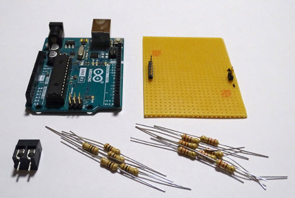
 You can turn a handful of parts into a digital-to-analog converter shield for the Arduino UNO.
Bill of Materials
Part/Qty
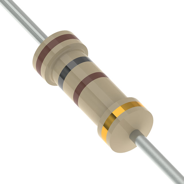
- 100 Ohm Resistor - 5
- 200 Ohm Resistor - 7
- Arduino UNO - 1
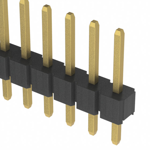
- Pin Header - 1
- Perfboard - 1
Understanding the Simple R-2R DAC Circuit
The R-2R resistor ladder is among the simplest and most cost-effective ways to convert digital signals consisting of multiple bits into a single analog output signal. The analog output signal represents the value encoded by the digital bits on a specific voltage range (for example, between 0V and 5V). If all bits are zero, the output should be zero. Similarly, the output should reach the maximum voltage value if all bits are set. Every value in between should produce a proportional analog output value, ideally in a linear fashion.
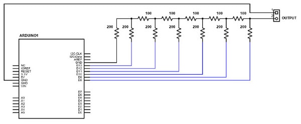
Consider the following schematic diagram that shows an Arduino UNO connected to a network of serial and parallel resistors that form the R-2R resistor ladder:
 This image shows the schematic of a 6-bit R-2R resistor ladder connected to the digital GPIO pins eight through thirteen of an Arduino UNO.
In its simplest form, the R-2R name refers to the resistor values. In this example, I chose 100 ohms for the R-resistors. Therefore, the 2R-resistors in the circuit had to have a value of 200 ohms. You could, in theory, extend the ladder to add more bits. However, the article will later discuss why that won’t work in practice. Note that you can also use two R-resistors in series to further cut down the number of different parts in your circuit.
The R-2R network arrangement causes the analog output signal’s voltage to move between 0V and 5V depending on which input bits are set. The output voltage is the weighted sum of the individual input bits, where the least-significant bit (LSB) has a much lower impact on the output voltage than the most-significant bit (MSB).
As this example illustrates a 6-bit resistor ladder, the LSB influences the final output by 0.078125V, which is 1/64 of the 5V input voltage used in this example. The next bit affects the output by 1/32 of the input voltage, which is 0.15625V. This pattern continues for all the other bits, and the MSB influences the resulting analog signal by 2.5V, which is 1/2 of 5V. Depending on which bits are set, you can calculate the final analog output voltage by adding up the respective proportional weighted voltage influence of all the set bits using the following formula:
 You can use this formula to calculate the resulting output voltage of a 6-bit R-2R resistor ladder DAC.
In the formula above, Va represents the LSB, and Vf denotes the MSB. Assume you set the bits b, d, and f. You can then obtain the desired output voltage as follows:
 This example shows the optimal output voltage of a 6-bit R-2R DAC, assuming the input voltage is 5V, and the bits b, d, and f are set.
You can then assemble the simple circuit on a piece of perfboard that matches the footprint of the Arduino UNO:
 This image shows the finished custom Arduino shield that contains the R-2R DAC.
Drawbacks of the Simple R-2R Resistor Ladder Circuit
The R-2R resistor ladder is one of the simplest and most cost-effective DAC solutions you can build. However, the simplicity of the circuit comes at a price. Unfortunately, the accuracy of the output signal greatly suffers the more input bits you add. To counter these inaccuracies, you’d have to use extremely expensive resistors with an unrealistically low tolerance. In addition, the resistors in the network need to be balanced so that they have similar values. These limitations make the simple R-2R resistor ladder a good choice for simple projects. However, the simple DAC is, unfortunately, not accurate enough for many more demanding applications, for example, video signal transmission:
 This oscilloscope screen capture shows the inaccuracy of my homemade R-2R resistor ladder that employs resistors with a tolerance of five percent. You can see how the output signal erroneously drops to zero volts at several points.
Generating Output Signals using the Arduino UNO
Upload the following sketch to the Arduino UNO once you’re done assembling the circuit:
#define RESOLUTION 6
#define MAX_VALUE 64

int outputs[RESOLUTION] = {13,12,11,10,9,8};
int vals[RESOLUTION];

void setup()
{
  for(int i = 0; i < RESOLUTION; i++)
	pinMode(outputs[i], OUTPUT);
}

void writeValue(int value)
{
  for(int u = 0; u < RESOLUTION; u++)
  {
	vals[u] = (value >> u) & 1;
	digitalWrite(outputs[u], vals[u]);
  }
}

void loop()
{

for(int i = 0; i < MAX_VALUE; i++)
	writeValue(i);
}
The setup method initializes the six GPIO pins used for sending the digital bits to the R-2R circuit. Next, the writeValue function takes an integer value as input and converts it to a binary pattern using the bitwise shift and binary AND operations. Lastly, the helper method outputs the calculated bit value using the corresponding digital pin. Finally, the loop method repeatedly calls the writeValue function to output all possible values between zero and 63.
Summary
The R-2R resistor ladder is an incredibly cost-effective and straightforward solution for converting digital signals to a single actual analog output. Using only a few resistors, you can add analog output capabilities to development boards that would typically not support proper analog output signals. Unfortunately, the simplicity of the R-2R ladder comes at the cost of reduced accuracy. In addition, you need to employ high-precision resistors, and adding more than five bits becomes infeasible.

Have questions or comments? Continue the conversation on TechForum, DigiKey's online community and technical resource.
Visit TechForum


 中国
中国