How to Connect the Particle Photon to External Circuits
2019-04-01 | By Maker.io Staff
The Particle Photon is a prototyping platform for IoT devices but is very similar to the Arduino range of development boards. In this How-To, we will learn about some of the pins on the Particle Photon board and how to connect circuits to the Particle Photon.
BOM
- Particle Photon
- Tactile Switch
- 10K Resistor
- 1K Resistor
- LED
- USB Micro B cable
Scheme-It

The Photon
The Particle Photon is a single-board microcontroller that is powered by an ARM Cortex M3 clocked at 120MHz. Capable of being programmed over the air (using an online IDE), the Photon is easily configurable and a very hobby-friendly device. Like the Arduino, the Photon has headers that are used to connect to external circuits, and these pins include power, digital signals, and analog signals. The function of each pin is directly printed onto the PCB, which makes identification of pins very easy, but some other functions (such as PWM) are not obvious.

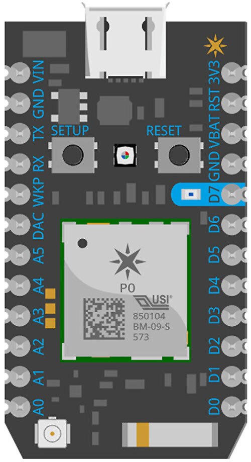
At a glance, we can see that the Photon has the following pins:
- 1 x VIN – Used to power the photon with an external 5V source
- 2 x GND – The common ground point
- 1 x TX – The serial port transmit out pin (you won’t use this in most projects)
- 1 x RX – The serial port receive in pin (you won’t use this in most projects)
- 1 x WKP – A digital pin for waking up the Photon module (you won’t use this in most projects)
- 1 x 3V3 – A 3.3V output that can be useful for powering external circuits
- 1 x VBAT – Used with a coin cell (1.6V to 3.6V) for the internal RTC (you won’t use this in most projects)
- 1 x RST – The reset pin (you won’t use this in most projects)
The most common pins you will use are the following:
- 6 x A – These (A0 – A5) are analog input pins and can read voltages
- 8 x D – These are digital pins that can be configured as either inputs or outputs
- 1 x DAC – This is an output pin
When using the Photon in a circuit, there are a number of ways you can power your project. The first, and easiest, is to use a micro USB-B cable and either connect the cable to a computer’s USB connector or a mains charger for devices such as phones and tablets. Connecting to a computer or laptop has the added advantage that the Photon is recognized as a virtual serial port that allows you to versatile communicate with the Photon from a terminal.
Another method for powering the Photon is to use the VIN input, which takes an external 5V source and internally regulates it to 3.3V for the Photon. However, this method is not useable in a number of projects that use batteries such as 9V and 12V types, and will, therefore, require an additional regulation stage (such as the use of a 7805 regulator). For most projects, it is best to use a micro USB cable.
I/O Considerations
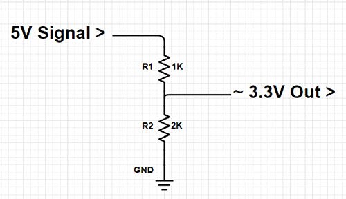
Unlike the Arduino Uno, the Particle Photon is a 3.3V device, which means that it cannot be used in 5V circuitry. While 3.3V outputs can drive 5V pins (remember, in the 5V realm a voltage greater than 2.7V is considered a logical high), 5V signals cannot be connected to Photon inputs (and doing so may permanently damage the Photon). Unless bi-directional communication is needed, a simple resistor divider can be used to convert a 5V signal to 3.3V for the photon. This way, a 5V device can communicate with the Photon without the need for any complex level-shifter ICs.

Reading / Writing to Digital Pins
Reading and writing to and from digital pins is done in an identical way to the Arduino Uno. Before a pin can be used, it first must be configured as either an input or output. This is done using the pinMode() function, which takes two parameters: the pin and whether it’s an input or output. One feature in particular about the Photon IDE that is helpful is the use of names to refer to pins such as D0 and A3, instead of having to find the pin number.
pinMode(D0, INPUT); // Configure D0 as a digital input pinMode(D1, OUTPUT); // Configure D1 as a digital output
Reading from digital pins is a very easy task, and is done using the digitalRead() function, which takes a single parameter - the pin being read. The function will return either 1 or 0 depending on the logic state of the pin, and these two refer to either a logical high (3.3V) or logical low (0V) signal respectively.
if(digitalRead(D0) == 1)
{
	Serial.println(“The input is on”);
}
else
{
	Serial.println(“The output is low”);
}
Writing to a digital pin is another trivial task that is done using the function digitalWrite(), which takes two parameters: the pin that is to be written to and its value. The value is either HIGH or LOW, and these two refer to either a logical high (3.3V) or logical low (0V) signal respectively.
digitalWrite(D1, HIGH);		// Set output D1 to 3.3V
digitalWrite(D1, LO
Our Simple Example
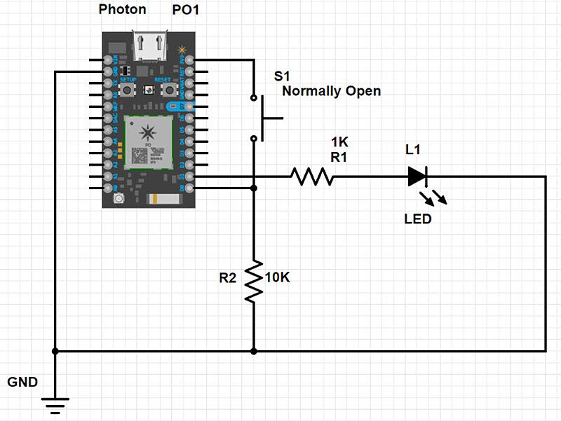
In our example, we have a Particle Photon that flashes an LED multiple times when it detects the push of an external tactile switch. A pull-down resistor (10K) is used, so that when the switch is left un-pressed, the pin D0 is connected to 0V through the resistor, which reads as 0V (to prevent the input from floating and producing unexpected results). When the switch is pressed, a direct path between 3.3V and D0 is made, so it is read as a logical high of 3.3V.
void setup()
{
    pinMode(D0, INPUT);         // Configure D0 as an input
    pinMode(D1, OUTPUT);        // Configure D1 as an output
}

void loop()
{
    // Read the switch connected to D0
    if(digitalRead(D0) == 1)
    {
        for(int i = 0; i < 10; i ++)
        {
            // Flash the LED 10 times
            delay(300);
            digitalWrite(D1, HIGH);
            delay(300);
            digitalWrite(D1, LOW);
        }

        // A 2 second delay!
        delay(2000);
    }
    else
    {
        // Do nothing, the LED is unpressed!
    }
}

Have questions or comments? Continue the conversation on TechForum, DigiKey's online community and technical resource.
Visit TechForum


 中国
中国