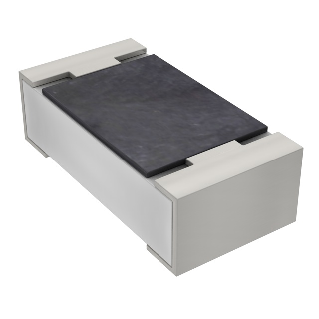
制造商零件编号 RC0603FR-0747KL
RES 47K OHM 1% 1/10W 0603
YAGEO
所订产品一般在 7-10个工作日 内送达中国,具体时间取决于收货地点。
最低订购金额为人民币 300 元,顺丰快递免运费配送。
当用人民币下单时,按照国际贸易条款 DDP(DigiKey 支付关税、海关费用和当地税款)方式结算。
电汇预付
![]()
![]()
![]()
更多来自全授权合作伙伴的产品
下单后,从合作伙伴发货平均需要时间 1-3 天,也可能产生额外运费。可能另外收取运费。 实际发货时间请留意产品详情页、购物车和结账页面上的说明。
国际贸易结算方式:CPT(交货时支付关税、海关费用和适用 VAT/应付税金)
有关详情,请访问帮助和支持
We have learned how to communicate with the micro:bit via a serial port, how to control NeoPixels, and about Adafruit IO. In this project, we will combine all three to create an IoT controlled NeoPixel using Adafruit IO, accessible with a modern browser on any device!
BOM
Scheme-It
![]()
You can find the full Scheme-It schematic for this project here.
The Plan
The plan for this project is to take advantage of a PC internet connection and serial connection to control a NeoPixel via a micro:bit. A PC is required because the micro:bit lacks an internet connection, but does have a serial connection. Commands can be sent from the PC to the micro:bit to control the NeoPixel.
The code for the micro:bit will be designed using MakeCode blocks, while the IoT software that runs on the PC will be written using Python (mainly due to the Adafruit IO libraries available). Since Adafruit IO dashboards can be publicly shared, we can use any device with a compatible web browser to see the status of the NeoPixels. However, only a logged-in individual can use the controls. Therefore, control of a dashboard appears to not be shareable.
The micro:bit Code
The first block to be executed is the “on start” block with several tasks. The first task is to create a NeoPixel object that uses 24 LEDs, the P1 pad, and in the GRB format for sending data. The second task is to redirect the serial port to USB. This is vital as it instructs the micro:bit to use the USB port as a serial port, allowing for easy PC communication. The third task is to set the brightness of the NeoPixel to 15. NeoPixels are incredibly bright and this reduces current consumption from the micro:bit. The last task is to clean the NeoPixel display to start in a known configuration.
![]()
The code for the micro:bit is rather simple and does not use the forever block, instead utilizing interrupt driven blocks. These blocks only operate when a specific event has occurred, such as “line received over the serial port.” If this occurs, the serial port data is read into a variable called “stringReceived” and a series of “if” comparisons determine the colour the NeoPixel becomes. The color value is sent via the serial port and the micro:bit program splits the incoming data stream into a color identifier (red, green, or blue), along with its specific value.
The Python Code
The Python application will be a middleman in this project and will not interact with any users at all. Instead, the Python programs job is to look for updates from Adafruit IO and then relay the new data to the micro:bit. This updates the NeoPixel to whatever is being instructed by the Adafruit IO dashboard. The incoming data from Adafruit IO is in the form of a hashtag color code, which first gets separated into the individual colors and then sent as a message with the color identified (red, green, or blue), followed by its value.
Copy CodeThe Adafruit IO Dashboard
The Adafruit IO dashboard only uses a single feed - “Color”- and a single dashboard object - the color picker. When the color picker object is selected, its color is changed using a color pallet. If the color option is saved, the color feed is also updated and the result is the NeoPixel changing color shortly after to match the color on the dashboard!
![]()

谢谢!
敬请关注收件箱中的 DigiKey 新闻与更新!
请输入电子邮件地址


