Another Ambassador Moment: H-Bridge Motor Control Circuits!
2022-11-04 | By Will Siffer
License: Attribution Non-commercial
Background
I was working on a circuit this weekend that was controlling a DC motor-driven linear actuator. While working through various designs for the circuit I remembered the MOSFET circuit I had learned in my motors class last year, the H-Bridge.
Named after the shape of the circuit, the H-bridge is a circuit that allows for a motor to have a varying speed and direction without having to actually change wires around! The chip I used for this project was a "TB6612FNG MOTOR DRIVER BOARD" from Digi-Key.com. This board is a breakout for the TB6612FNG that allows for prototyping on a breadboard and can control motors with low-current applications.
What do you need to try this out?
For this project you will need:
- 1 TB6612FNG motor driver board or similar h-bridge circuit
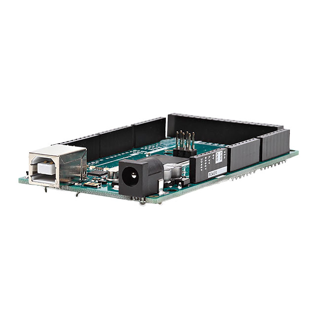
- 1 Arduino, I used the Arduino Mega for this project but any will work and the Mega is definitely overkill for this application
- 1 Breadboard
- A handful of jumper wires
- 1 small DC motor
What do you need to do to get started?
The H-bridge is a fairly easy circuit to understand, and the video above definitely explains the device in greater detail. Below is the circuit layout of the H-Bridge:
The general rule is that you only power 2 switches at a time, on diagonal sides. So powering S1 and S4 would cause current to flow left to right in the motor. Alternatively, you can power S3 and S2 while opening S1 and S4 and the current will flow right to left in the motor, causing a spin in the opposite direction as before. If you power just one of the switches, the motor will stop moving and coast. Finally, if you power S1+S2 or S3+S4 you will short the power supply and possibly damage other components, so avoid that always!
For the Arduino, I used this code below:
int in1A = 3;
int in2A = 4;

void setup()

{
  // Set all the motor control pins to outputs
  pinMode(in1A, OUTPUT);
  pinMode(in2A, OUTPUT);
}

void loop() {
  analogWrite(2, 45);
  //Set motor forward
  digitalWrite(in1A, HIGH);
  digitalWrite(in2A, LOW);
  delay(2000);
  //Stop motor
  digitalWrite(in1A, LOW);
  digitalWrite(in2A, LOW);
  delay(2000);
  //Set motor reverse
  digitalWrite(in1A, LOW);
  digitalWrite(in2A, HIGH);
  delay(2000);
  //Stop motor
  digitalWrite(in1A, LOW);
  digitalWrite(in2A, LOW);
  delay(2000);
}
The motor controller I used only had 2 control pins rather than 4 and a speed pin. It was kind of like having only control over the S1 and S3 switches, with the controller automatically selecting S2 and S4 to produce valid motion. You can see in my code how I flip which pins are high and which are low in order to change the direction of the motor.
I hope you learned something from this circuit! I know it's one of my favorites for directional current control for motors and actuators!

Have questions or comments? Continue the conversation on TechForum, DigiKey's online community and technical resource.
Visit TechForum


 中国
中国