制造商零件编号 746
ULTIMATE GPS PA1616S BREAKOUT
Adafruit Industries LLC
Microcontrollers Temperature Humidity Wireless Bluetooth / BLE GPS
What engineering project could be cooler than a robot that fixes a real-life problem? Even better if it saves money for small businesses.
Our engineering professor told us that, when he had been a beekeeper, he had rented a bobcat-like vehicle to move his beehives from his apiary to crop fields for pollination. Rent for less than a month cost him tens of thousands of dollars. “There’s no reason we can’t mass-produce robots to do this for less than $250 each,” our professor thought.
Our first prototype would get us “in the ballpark” of the final product he had imagined. We wanted to build 1/6-scale prototypes and set our prototype budget at $400. However, we set several challenging goals: building a moving tank-tread robot with motors and drivers, using SolidWorks and a 3D printer for the robot’s body, crafting a power, and charging system from components, handling temperature/humidity/location data, troubleshooting Bluetooth communication between controllers and the robot, and programming self-driving and waypoint-making.
If we mass-produced the robot, we envisioned each robot would permanently “live with” four hives on its “back.” The operator would input instructions to drive onto a trailer, leave the trailer at the destination, and drive to specific coordinates from the beekeeper’s pollination customer.
On our team of four people, I worked on our GPS and temperature/humidity chip, in addition to the group tasks and documentation. My team CEO William needed temperature, humidity, and location data to display on the app he used, and our CFO Luke needed location, direction, and speed data to program his self-driving features.
We spent most of our first semester writing documentation to plan the project and engineering small projects to understand our power system and communication protocol. Specifically, we practiced breadboarding I2C communication with tiny microcontrollers and building a power system from components, based on a LM353 op-amp. Since we could not use power directly from an outlet, we needed random noise protection and a regulator to ensure the voltage and current stayed stable enough to protect the chip.
Most importantly, in the planning phase, we had to choose our chips. For location, speed, and direction data, I chose the Adafruit Ultimate GPS based on the PA1616S chip. This breakout had all the data I needed, and, since our team’s microcontroller had an extra UART port unused, the UART communication used by the Ultimate GPS would work well. As a bonus, although the Ultimate GPS can use an additional external antenna, the internal antenna worked well enough for my project’s purposes. For temperature and humidity, I chose the DFRobot DHT22 based on Aosong’s AM2302 chip. The DHT22 had a cheaper price tag than many modules I researched, and the DHT22 had superior accuracy compared to the DHT11, the other chip I considered. It also only used a single GPIO [general-purpose input/output] pin for serial communication, which would conserve the few specialty pins our microcontroller had.
The parts that each team chose either haunted them or helped them during the entire project. For the subsystem to work correctly, the voltage level, input current, and type of port all need to match, from microcontroller to module. While this sounds complicated, with a bit of practice, these requirements only need to take a handful of minutes to check. Most chips use either 3.3V or 5V, and we can use a voltage regulator to change from one to the other. As a general rule, I would suggest picking one and sticking with it. For input current, we only need to use the search feature on our PDF viewer to look for ‘input current’ in the datasheet and see how many amps each chip can handle. The port causes the most issues, but, again, a simple search through the datasheet for ‘I2C’, ‘SPI’, or similar communication types will easily help us.
The two-part class began in August, but, due to a long planning phase, we did not start design until the following February. We used OrCAD Capture to draw the schematics for our subsystems, and we imported those schematics into OrCAD PCB Editor to create the design for the PCB “printer” to actually make the circuit boards.
The OrCAD Capture schematics help us see how the different pieces of the circuit fit together and where the wire connections sit. In circuit theory, we call each group of wires separated by elements—such as resistors, capacitors, or any chip—a ‘node.’ Since we know about nodes, we know we can move the wires any way we want, as long as we don’t connect this wire node to any side of an element where it is not already connected. Mario de Lorenzo’s article “Electronics Laws Overview Theories and Practical Use Cases” and “Kirchhoff’s Current Law (KCL)” on All About Circuits would both be great articles to expand your practical knowledge on node-related principles.
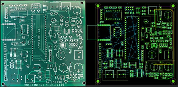
The shapes we see on the PCB design (see below, right above Software Design) do two things. The shapes both reserve space on the PCB and help the computer automatically connect your elements with route copper traces—which function as wires in the PCB. After we confirm that we like the wire paths that the software picked, we still need to solder the elements onto the PCB, but, otherwise, the PCB software has done most of the work for us! No poking fifty different wires into a breadboard!
I would still recommend breadboarding some important pieces of your design to test them, but, honestly, in this project, my team did not have time.
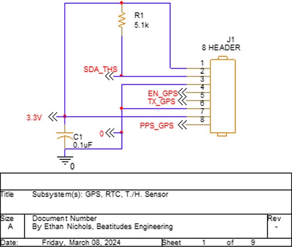
To be most effective against noise, the bypass capacitor shown below should actually be as close as possible to the header. You can read “Clean Power for Every IC, Part 1: Understanding Bypass Capacitors” on All About Circuits for more information. For the resistor, I knew where to put it, why, and what value based on the datasheet for the DHT22. SDA is the data output of the sensor, EN allows the user to quickly shut off the GPS to save power. PPS gives one pulse-per-second to allow the user to sync their data with the time. I did not end up using the GPS pins EN or PPS due to lack of time.
 OrCAD Schematic for Temperature, Humidity, and GPS
The OrCAD PCB Editor design allows us to visualize the placement of physical components. Footprints serve as instructions for the PCB manufacturer, guiding the etching of lines to indicate where to solder the components onto the board. These footprints also feature specially designed holes for placing the chips, with connections to other footprints, power, and ground to support our design. Each of my GPS and other chips required power, ground, and data output. I consolidated them onto a single 8-pin header, adding EN and PPS pins for the GPS in case I needed them in the future.
In the OrCAD PCB Editor, the blue lines represent two pins that need a copper trace routed between them.
 Final PCB Compared to the OrCAD PCB File for the Robot
I would not suggest scheduling only two weeks to code all your C Language software, even if you have four teammates. However, since we had much to learn about OrCAD PCB Editor, PCB ordering, and the knowledge we needed for our individual subsystems, we had to make do.
For my software, I had two subsystems: GPS and temperature/humidity. For the Adafruit Ultimate GPS I used, it sends approximately 1500 ASCII characters every second; my GPS program only needed to parse the data—find the data I wanted from the 1500 characters—and convert it to doubles for my teammates Luke and William to use. While the GPS sent many pieces of data, my teammates only wanted the coordinates, speed, and direction data so William could display it in the app and Luke could use it for the self-driving algorithm.
The temperature/humidity software worked similarly to the GPS software, with one exception: the DHT22 uses a different kind of serial communication, not I2C. I had to carefully read through the DHT22 datasheet to make sure the microcontroller “talking” to the DHT22 gave the right “handshake” and received the right “handshake” back. Luckily, C Language and my PIC18 microcontroller had low-level commands that allowed me to directly turn the power on and off to the GPIO pin for each part of the “handshake.”
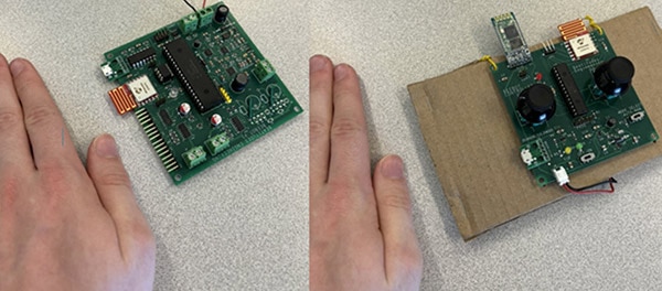
 Robot PCB (Left) and Controller PCB (Right), Both with Components (Hand for Size Reference)
Testing felt the most nerve-wracking…and the most exciting! Testing happens too late to change most features, but we felt so satisfied when we saw a project that lived so long in our heads become a reality!
Our team scheduled a time with our professor to test the robot. Our robot could not self-drive and could not use the solar panel. However, the Bluetooth remote, which William had designed, worked flawlessly, as did the app he had configured to receive temperature, humidity, and location data.
One of our project requirements stated that our robot would be waterproof. We bought components for the robot itself that claimed they would work despite water, and, per our requirements list, we had the robot drive while we poured a gallon of water on it. Water causes problems when the conductive particles that float inside the water connect parts of the circuit that are not supposed to be connected. For this reason, we used distilled water along with our ‘waterproof’ parts to help avoid failing the test. And we passed! The robot kept moving, even after we poured a gallon of water on it. We also drove it through a Pensacola downpour later, and the robot had no issues.
 Robot, Disassembled to Dry, after the Rain Test
We felt some disappointment that we only met 45 out of 66 requirements; however, all 21 of those missed requirements pertained to either self-driving or the solar panel. Programming self-driving feels incredibly rewarding; however, with an already long project, we just did not have time. If I can make the scope of my next project smaller, I will. I can always add more later!
 Final Prototype