Building a Voice-Controlled Robot - Linear Models and Machine Learning
2024-07-31 | By Annabel Ng
In the previous blog post for this project, I covered the basics of the circuits necessary to run the robot’s motors, process audio signals, and regulate the voltage. However, the robot is not quite done yet! Although the robot can properly move its wheels and recognize audio signals, it still can’t be controlled by voice commands or drive in predefined paths.
Linear Control Models
The first thing to tackle is implementing a straight-line drive. To do this, we use a linear model to control the voltage supplied to the wheels. Using a linear model is appropriate for modeling the car system because a linear system is much easier to analyze, and we can estimate the real system by finding an operating point with an approximately linear behavior. For each of our wheels, we use the following model, where v represents velocity, d represents the number of ticks measured by the encoder, u represents the delivered voltage from the PWM signal, theta represents the change in input voltage to change in velocity to change, and beta represents some constant.

To test different velocities for data collection, we vary the duty cycles of pulse width modulation signals (PWM), which are square waves with variable “on” time. These duty cycles represent the percentage of time the signal spends on, allowing us to control the average voltage of the PWM signal. This is especially useful for systems like motors, and you can read more about PWM cycles here! For example, a 5V signal with a duty cycle of 0.75 creates an average voltage of 3.75 V, so by cycling through different duty cycles, we can easily test the effect of different specific voltages on the velocity of our car.
Least Squares
In order to choose our operating velocity to drive our robot straight, we first collect some coarse wheel velocity data from 50 to 250 PWM cycle, then look at the graph of data to eyeball an approximate linear range of data. After identifying a specific PWM range, we rerun the data collection and apply a least squares model to the left and right wheel velocities. Least squares works by finding a linear equation that minimizes the squared distance to the given data points. This least squares model allows us to control our input PWM voltage and thus linearly control our velocities.

Closed-loop Feedback
However, least squares is an open loop system, meaning it doesn’t respond to external feedback. This open loop system caused the robot to drive in a circle rather than the desired straight line. Once we incorporate a feedback variable into our system to make it a closed-loop system, both wheels drive at equal velocities, causing the car to go straight. Our closed-loop system must be stable, which means that the system eigenvalue must have a magnitude less than 1. Lastly, to implement turning, we had to take the geometry of an arc and take into account the difference in distance traveled between the left and right wheel.
Now that our robot can drive straight and turn left and right, the next step is to build a voice classification model. Since different words have different waveforms, we chose 4 words with distinct syllables and sounds in order to produce distinct waveforms. We recorded our words 50 times each using the microphone on the robot, preprocessed the data, then split the data into train and test splits. We built a matrix by stacking the data vertically, demeaning the data, and taking the singular value decomposition (SVD) of this data.
This is the SVD equation for decomposing any matrix:

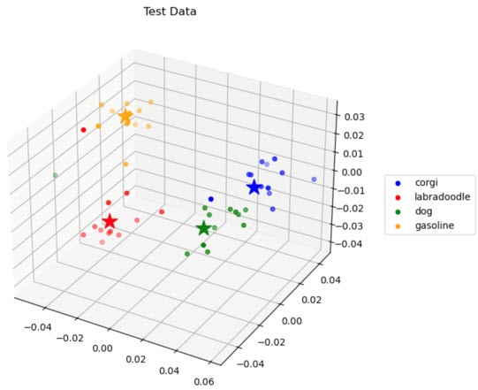
Taking the SVD of our data allows us to find the “essence” of our data, or the data that’s most important to reconstruct our data from scratch. We can find these important components by choosing the first 3 principal components as a new matrix basis. After projecting our data onto this new basis, the data splits into distinct clusters, allowing us to find the center of each cluster, also known as the centroid. We then use these centroids to classify our test points: classification works by finding the Euclidean distance from a test point to a centroid and comparing it to a threshold – if the distance is less than the threshold, then the point will be classified as the same class as that specific centroid. Once we had a strong model accuracy, we used this model on our Arduino to test live classification.
Here's an image of the clusters of our four chosen words: dog, labradoodle, corgi, gasoline. The clusters are quite distinct and separated, making it easy to create an accurate classification model based on Euclidean distance.

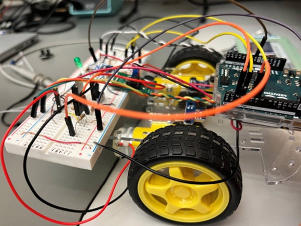
After the robot could successfully run in a straight line and turn in different directions, as well as classify voice commands, it was time to combine everything together. Integration involved adding the motion commands into the classification program, so if the Arduino classified a word as “straight,” the corresponding motion would be to drive straight. After lots of testing and tweaking the loudness and Euclidean threshold, our robot finally worked! This was the culmination of a whole semester learning about circuits, control systems, and PCA, and it was very cool to see it in action.
Here's an image of the completed robot!

If I were to do this project again, I would try to go into it with a more high-level perspective rather than always trying to focus on the smaller details. Sometimes I got so caught up in actually building the circuit or coding the algorithm that I forgot what the role of the circuit was in the bigger picture, and it wasn't until the very end that I had a better appreciation for all the components that went into this project. Some weeks I also dreaded the labs because I knew it would take the full three hours of the lab or even more, but I would remind myself of the end product and how grateful I am for the opportunity to apply my learnings to this project!
Special shoutout to my lab partner, Eric Wen, who’s also an EECS student at UC Berkeley, as well as to course staff who made learning all this content possible! All figures are from the official https://www.eecs16b.org/ website.

Have questions or comments? Continue the conversation on TechForum, DigiKey's online community and technical resource.
Visit TechForum


 中国
中国