Building a Formula Car: BSPD Part 2
2024-09-11 | By Antonio Velasco
Continuing to the second part of the UCI FSAE team's process of completing a Brake System Plausibility Device (or BSPD) design, we look into how such a safety circuit works and the requirements behind it. The goal is to utilize this system throughout multiple competitions through the next year, such as the 2024 SoCal Shootout and the 2025 Formula SAE Michigan competition!
The Requirements and Design
As stipulated by the FSAE rulebook 2024, these aspects need to be covered for the 3 different implausibilities that the BSPD needs to detect:
- Hard Braking and open throttle for 1 second.
- Loss of brake pressure readings for 100 milliseconds.
- Loss of Electronic throttle body readings for 100 milliseconds.
Essentially, the BSPD’s design has to compute 2 key aspects entirely with analog components.
- The comparison between the brake pressure sensor and electronic throttle body voltage readings is used to check for implausibilities or rule-specific conditions.
- A time delay between a found implausibility of either 1 second or 100 milliseconds.
The Approach
These aspects of the BSPD, comparison of sensor readings and time delay are done in two parts. Firstly, the comparison between sensor readings. Let's take the condition of “Loss of brake pressure readings for 100 milliseconds” as an example.

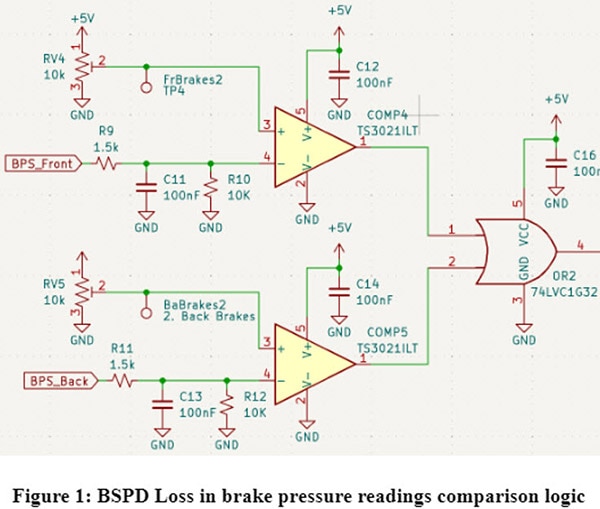
The comparison for valid and invalid sensor readings is done through comparators. As shown in Figure 1, the comparators will either output 5V or GND based on whether the positive input of the comparator is higher than the negative input. For the BSPD, the negative terminal is the signal from a brake pressure sensor, which outputs a voltage between 0.5 ~ 4.5. This signal is put through a low-pass filter for noise filtering and then compared with the comparator. A potentiometer is then used as a voltage divider and is connected to the positive terminal of the comparator with its 2nd terminal set to about 0.45V. This setup makes it so that the comparator will only output high when the brake pressure dips below its normal voltage output range of 0.5V ~ 4.5V, meaning an implausibility will be found when a comparator outputs a HIGH signal. The signal passes through an OR gate to allow for a setup of 2 comparators and is sent to the time delay section of our circuit.

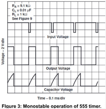
The time delay of 100 ms is done mainly through a 555 timer in a monostable operation. As shown in Figure 2, the implausibility of HIGH 5v is sent through the NOT gate and into the TRIG pin of the 555 timer. With the monostable operation circuit for the 555 timer, the OUT port of the 555 timer will be pulled high, as shown in Figure 3, and then promptly inverted by the NOT gate connected to the OUT port. This is done to introduce a time delay of any time by the resistance value set by the potentiometer RV8. This signal coming out from the 555 timer needs to be “compared” to the output of the OR gate in Figure 1, to see if there is still an implausibility from the comparators after 100 milliseconds.

There comes a problem, since the output NOT2B will naturally be HIGH when there is no implausibility and will only output a LOW during the time delay of an implausibility, there’s a small chance that with time propagation delays an implausibility signal could be sent out of the AND gate for a small period while the 555 timer is attempting to pull up its OUT pin. To mitigate this possible error, a small delay is introduced between the output of the OR gate in Figure 1 and the input of the AND gate in Figure 2. The RC time delay should give plenty of time for the 555 timer’s propagation delay. Finally, if the OR gate is still outputting a HIGH after the time delay of the 555 timer, both inputs into the final AND gate in Figure 2 will be set to HIGH. An implausibility condition has been found, and the signal is sent to shut off a series of relays to shut off the engine of the car.

With the other implausibility circuits, shutdown circuits, and power circuits, we get our final PCB in Figure 4. Testing/fabrication is already underway, and the next blog will be about how troubleshooting the design went. Thanks for reading!
~Anteater Formula Racing
Have questions or comments? Continue the conversation on TechForum, DigiKey's online community and technical resource.


