Building a Formula Car: BSPD Part 1
2024-08-23 | By Antonio Velasco
Anteater Formula Racing is a student-run engineering project at UC Irvine. The objective is to design, manufacture, and test a Formula-style car in less than a year to compete yearly in the Formula Society of Automotive Engineers competition in Michigan (FSAE). Once in Michigan, the car is judged by industry professionals against a variety of criteria, including static/dynamic events, presentation, engineering design, and many more. Anteater Formula Racing consists of approximately fifty students from varying engineering backgrounds working on different vehicle subsystems ranging from chassis, suspension, aerodynamics, electronics, and many more.
Of the many complex systems, the team is designing in the car, the team decided to specifically run an electronic throttle control system. However, in order to use an electronic control system, the team must develop a Brake System Plausibility Device (BSPD) - a required safety circuit per the FSAE rules. More specifically, the BSPD is a standalone non-programmable circuit that is used to monitor the electronic throttle control. The BSPD monitors multiple conditions, such as:
- Hard braking and throttle open by 10% for more than one second
- Loss of signal from brake pressure sensors for 100 msec
- Loss of signal from the throttle sensors for more than 100 msec
- Removal of power from the BSPD circuit.
If the BSPD experiences any of the aforementioned conditions, the car must immediately shut down. More specifically, the engine must shut off and disconnect power to the fuel pumps, ignition, and electronic throttle control.

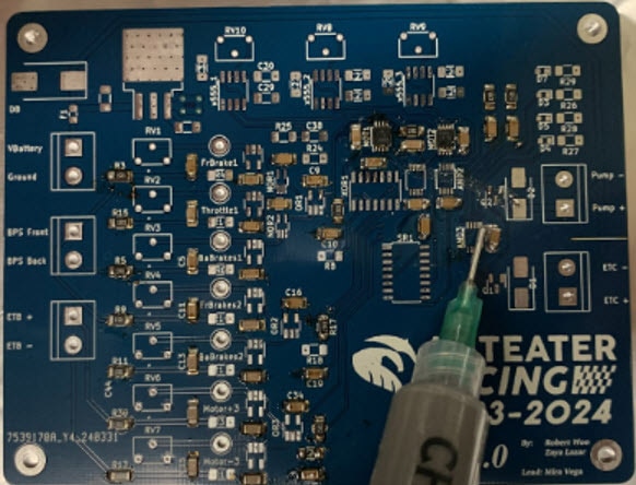
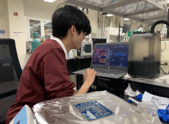
For the past couple of months, the electronics subteam has been designing a complex PCB to accommodate all the FSAE regulations to specifically monitor various sensor conditions and achieve shutoff. The BSPD design is a fully analog PCB, utilizing a combination of surface mount and through-hole components. The design requires using a multitude of capacitors, diodes, LEDs, fuses, resistors, logic gates, voltage regulators, 555 timers, MOSFETs, and potentiometers. Additionally, the design requires the BSPD to receive inputs from two brake pressure sensors.
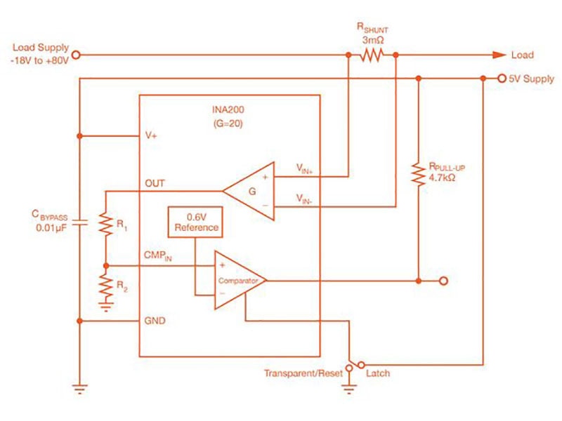
Regarding the specifics of the design, the signals of the brake pressure sensors and electronic throttle control are monitored through comparators. If any of the sensors are outside their normal operating range for more than 100 msec then the car must shut off. For the BSPD to monitor the timing requirement, the design uses 555 timers. The outputs of the BSPD are connected to normally opened relays, which are then connected to the fuel pump and electronic throttle body. Under normal conditions, the BSPD inputs and outputs 12V constantly to the relays. If an implausibility occurred, the voltage would be cut off through a series of MOSFETs. Additionally, if any of the conditions are triggered, then an LED lights up.

As the design for the BSPD has been finalized, the manufacturing phase has started. The manufacturing involves soldering all the surface mount and through-hole components over one week. After finishing manufacturing, the BSPD will undergo rigorous testing to make sure the system is fully rules compliant, testing each condition individually using voltage sources and an oscilloscope to ensure the 100 msec timing is achieved.
Throughout this series, we'll take you under the hood of how this system is developed, manufactured, and created from scratch! Stay tuned!
~Anteater Formula Racing
Have questions or comments? Continue the conversation on TechForum, DigiKey's online community and technical resource.


