Introduction to Current Shunt Monitors
2016-02-12 | By Dave Knight
Current shunt monitors are a simple and easy way to measure current. This article introduces the ideas of current shunt sensing, some current shunt ICs, considerations when designing a current shunt monitor, and applications.
Current shunt monitors measure the voltage across a sense resistor placed in the conduction path between a power source and a load. This voltage is multiplied by a gain either fixed in the IC or programmable by external resistors. This is demonstrated in figure 1, the simplified application schematic for Texas Instrument’s INA195.
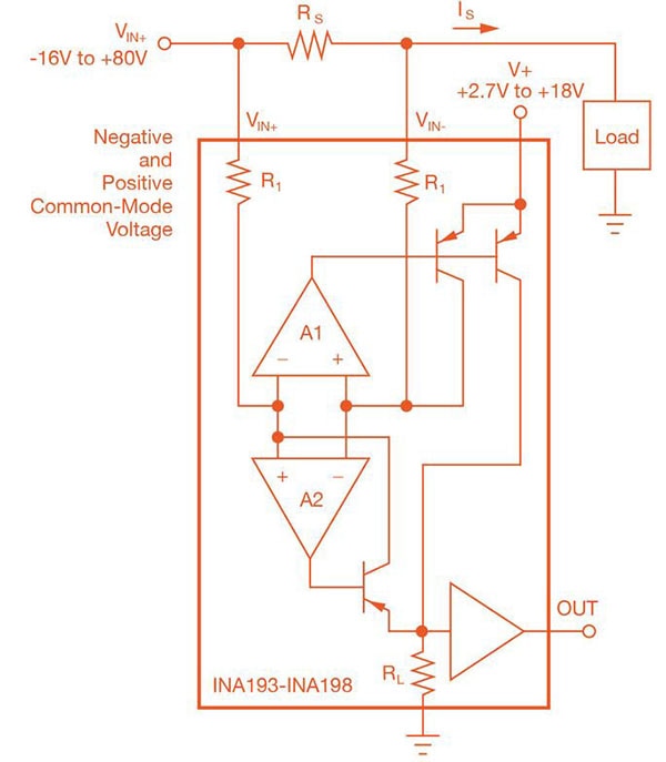 Figure 1: Simplified INA195 application schematic
Image Source: http://www.ti.com/lit/ds/symlink/ina195.pdf
The INA195 has a fixed gain of 100 V/V. This means that the output voltage will be 100 times the voltage across the current sense resistor. Current measurements can be taken from a node from -16 V to 80 V. The INA195 is part of a family of current shunt monitors that have fixed gains of 20 V/V, 50 V/V, and 100 V/V. The INA19x family requires 2.7–18 V to be connected to the V+ pin to power the internal circuitry. One of the advantages of having an extra pin to power the internal circuitry is that the current can be sensed even when the load is a short circuit to ground. Not all current shunt monitors can do this.
Diodes, Inc.’s ZXCT1009 is a current shunt monitor with many differences from the INA19x family. Two of the main differences are that the ZXCT1009 pulls its operating power from its VSENSE+ pin. The ZXCT1009 operates over a voltage of 2.5 V to 20 V. Because it draws its operating power from the line voltage, it cannot measure current into a shorted load. The ZXCT1009 is good for applications where the output will never be below 2.5 V. It comes in a small SOT-23-3 package.
The ZXCT1009 is also different because it has programmable gain. The gain of the ZXCT1009’s internal amplifier is set by an external resistor between IOUT and ground.
 Figure 2: Simplified ZXCT1009 application schematic
Image Source: http://www.diodes.com/datasheets/ZXCT1009.pdf
Texas Instruments provides another interesting family of current shunt monitor ICs. The INA200/1/2 family is like the INA19x, but includes a programmable current limit and comparator with an open drain output. Figure 3 is the typical application schematic for the INA200. Figure 4 shows a cool way of using the INA200 to disconnect the load from a power source in case of an overcurrent fault condition. This kind of circuit is valuable in applications where a decision has to be made more quickly than software can operate.
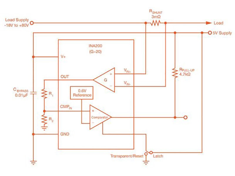 Figure 3:INA200 typical application schematic
Image Source: http://www.ti.com/lit/ds/symlink/ina202.pdf
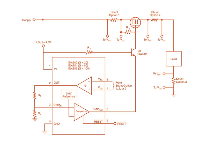 Figure 4:INA200 application schematic with resettable overcurrent load disconnect
Image Source: http://www.ti.com/lit/ds/symlink/ina202.pdf
Considerations in choosing a current shunt monitor
Choose a current shunt monitor based on its voltage rating and gain. Another very important consideration is whether the load can ever be a short to ground. If it can, then use a current shunt monitor with an external VCC pin. If not, you can save some PCB space by using a current shunt monitor that draws its power from the terminals connected to the sense resistor.
Be careful in choosing the current sense resistor. Choose as small a resistance as possible to minimize the voltage drop (V=IR) between the power source and the load. Also, use a package that is big enough to dissipate the heat (P=I*R) generated in the resistor. Also consider that using a resistance that is too small gives you a very small sense voltage, which will decrease the accuracy of your measurement. Datasheets typically include tables that tell you how accurate your measurement will be based on the sensing voltage.
When doing layout, make sure that the sense pins go directly to the sense of the sense resistor to get an accurate reading. This is called a Kelvin connection.
Applications
Several off-the-shelf battery charger ICs, battery gas gauges, and LED driver ICs use a current shunt sense resistor. A current sense monitor can be used to monitor the current going into a motor, or out of a power supply.
A current shunt IC’s output can be connected to an op-amp in part of a control loop, or go into an ADC to be used in a decision made by a microcontroller.
Applications include power management, welding, lighting, cellphones, telecom, battery chargers, automotive, and more.
Conclusion
This paper has discussed current shunt monitors, some commercially available ICs, considerations in choosing a current shunt IC and current sense resistor, and applications. For more information on current sense monitors, visit DigiKey.


