Using I2C with an Arduino Interface
2023-11-24 | By Andrew Chen
This tutorial will cover how to use I2C to effectively communicate between multiple devices on a bus network.
To fully utilize I2C to its maximum, we need to understand what is I2C and what makes it different from the other communication protocols that we can use to communicate between different devices. I2C (Inter-Integrated Circuit) is a communication protocol widely used in electronics and devices. It connects devices using two wires: one for data and one for a clock signal. One device or more can be designated to act as the "controller" and control communication, while the others are "peripherals." Data is sent in packets with start and stop signals. Each device has a unique address, allowing the controller to talk to specific peripherals. I2C is popular for its simplicity and is used in systems where devices need to exchange data within a short range, like in sensors and microcontrollers.
In this example, I'll be using the Arduino Micro and the MCP4728 board from Adafruit, both of which are available from DigiKey.

Here I'll designate my Arduino microcontroller as the controller device, and the digital-to-analog converter as the peripheral device. Let's look at their pinouts and see where we need to wire them:

Here we are really only interested in which pins are the SDA and SCL (PD1 and PD0 respectively on the right of the device); as mentioned before, we want to look for the two wires that transmit data and generate a clock signal. SDA and SCL are short for serial data and serial clock. We will work with these lines to communicate between the two devices. Now, let's look at the MCP4728 board and see its pinouts:

On the lower half of the MCP4728 chip breakout board, you can see that there are also corresponding SCL and SDA pins on the left-hand side and that's where we will connect the Arduino Micro SDA and SCL pins to these two pins. We also need to connect VCC with at least 3.3 Volts (up to 5 Volts) and connect GND to allow the MCP4728 to power. The Va, Vb, Vc, and Vd pins are the output channels where it will supply voltage. As for demonstration purposes, the LDAC and RDY pins aren't used but LDAC is a latching pin that latches onto the output while data is being transmitted, and RDY is a pin that alerts us when the MCP4728 is currently writing to EEPROM or not.

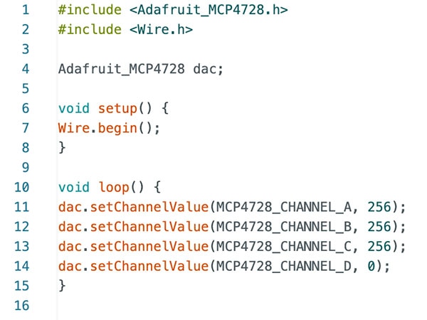
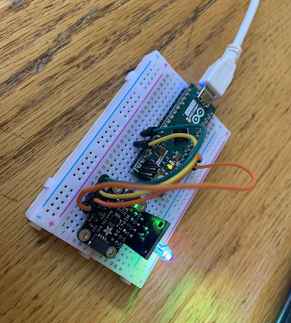
Cool! We got the MCP4728 to turn on, which is indicated by the green light next to the "ON" text on the board! Nice, but how do we communicate with this device and do something meaningful with it? This is where the software side comes into play, and we can program some really cool stuff through the Arduino IDE:
Here, we are going to use the Wire library to start up the I2C communication between our Arduino Micro and the MCP4728 DAC. In our void setup section, we are going to initialize the communication line between the Arduino and the peripheral device by using Wire.begin(), which begins the transmission of data between the Arduino and the MCP4728. This interface is what makes the Arduino Micro the controller device because the software allows the user to manipulate any device from within the Arduino itself.
But what good is this if our devices only know the other one exists? What cool stuff can we do with this information?

Normally without the Arduino IDE, we can't really do much with the MCP4728 itself since it is just a DAC after all, so we will need to pass in some information from our side to get it to do things we want it to do.
Here, I've also included the Adafruit_MCP4728.h library in order to use more functionality and commands specific to the MCP4728 chip. By initializing the chip as an "Adafruit_MCP4728" data type (if you think about it like that), we can call special methods that utilize I2C that are not available without this library on this variable. The special method here is the setChannelValue(), which looks very simple but there's actually a lot of abstraction hidden inside the method that allows it to communicate via I2C. To see how it relates to I2C and the SDA and SCL pins, let's see what the method does specifically from the perspective of I2C:

The SCL signal works with all the Wire commands since all data management is effectively managed by the SCL signal, which is not explicitly stated in the code. The SCL signal ensures that the peripheral is receiving data at the correct time and rate between peripheral and controller devices and that data transfer is always synchronized. In systems where there may be multiple controllers, the SCL signal also ensures that only one controller is communicating at a time to avoid data collision/corruption.
Let's look at all the Wire commands in this abstraction because that's where we are directly working with SDA (or serial data) to communicate to the MCP4728. In I2C, the data being transmitted to the peripheral device consists of three 8-bit (or byte) sequences; the first one is the peripheral address itself (which the parameter is taken by the Wire.beginTransmission() function). After the first byte, the second byte contains information about the internal registers of the peripheral device, which is then finally followed by the actual data until the transmission ends with a special stop condition. Then, we begin the first level of data transmission by using the Wire.write() method, which gives the MCP4728 special instructions. In this case, the three Wire.write() methods set the channel to an output voltage specified by the input parameter value. In this specific case, the setChannelValue() sets the output of the channel to be the value, which can be used to power an RGB LED.

Here the output channel A is connected to the B value, the output channel B is connected to the G value, and the output channel C is connected to the R value. After uploading the code onto the Arduino, we can see that the RGB LED is indeed turned on, and if you look even closer, all three lights are turned on because we specifically told the LED to light up for all three values.
And that's the basics of I2C down to a simple and fundamental level! However, if we were to implement the I2C by typing out the entire bit-banging process from scratch, it would be time-consuming but effective for those who want extremely specific operations. Many devices with an I2C interface already have built-in commands included in their library that already cover the I2C communication semantics for you. However, it's still good to know what's really going on behind the scenes to be able to apply I2C in more advanced situations. This tutorial only serves to give the general basics of what I2C is, and its importance in communicating across different devices, and the why and how devices talk to each other.
Until next time,
Andrew

Have questions or comments? Continue the conversation on TechForum, DigiKey's online community and technical resource.
Visit TechForum


 中国
中国