How to Use a Phototransistor with an Arduino
2022-11-30 | By Maker.io Staff
A phototransistor is an active semiconductor component that can detect various light levels with fast response times. The response time of the phototransistor is 1 - 10 microseconds (µs). The response curve of a phototransistor has a broad wavelength range, from the near-ultraviolet, visible, and near-infrared parts of the electromagnetic spectrum. Therefore, the phototransistor can be used in various light detection circuits and devices.
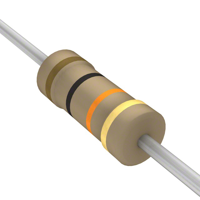
 A typical phototransistor
The phototransistor’s wavelength spectrum is shown below.
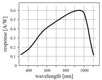 Phototransistor wavelength spectrum
A noteworthy characteristic of the phototransistor wavelength chart above is the nonlinear shape curve. This nonlinear output response allows the phototransistor to respond to various light levels expediently.
There are lots of applications that could use phototransistors, for example, a sunrise alarm clock. Upon detecting the sun’s light rays, the phototransistor may be used to provide an audible or visual alarm alerting the user that it is morning. But how do we wire a phototransistor to an Arduino to create a Light Activated LED fader effect?
Wiring a Phototransistor to an Arduino Uno
Building a light-activated LED fader effect requires wiring a phototransistor to an Arduino. The two primary leads of the phototransistor are the collector (C) and the emitter (E). The phototransistor C-lead will be wired to the Arduino Uno’s +5V pin, while the phototransistor's E-lead will be wired in series to the Arduino Uno’s ground (GND) through a 10KΩ fixed resistor. Where the two components are attached to each other, a jumper wire will be used to provide a continuously varying voltage signal to the Arduino Uno’s analog-to-digital converter (ADC) on pin A0. The ADC pin reads the various voltage levels produced by the phototransistor. A visual indicator consisting of a series current-limiting resistor wired to a blue LED is attached to digital pin D9 of the Arduino Uno. See below for the light-activated LED fader wiring diagram.
 The Light Activated LED fader electrical circuit wiring diagram
The electrical wiring diagram labeled the key termination points, the blue LED, and the phototransistor leads. You can use the schematic diagram below as you’re working on this:
 Scheme-It Light Activated LED fader circuit schematic diagram
Your circuit should look similar to the below design when you’re done:
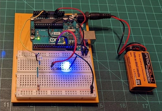 Functional Light Activated LED fader device
Light Activated LED fader code
With the wiring complete, upload the Light Activate LED fader code to the Arduino Uno. Open the Arduino Integrated Development Environment (IDE) and use the code shown below. The blue LED’s intensity will align appropriately, depending on the ambient light level. Experiment with various light levels using external light sources with the movement of your hand.
// Setup serial port baud rate and define INPUT and OUTPUT pins
void setup()
{Serial.begin(9600)}
 pinMode(blueSensorPin, INPUT);
 pinMode(blueLEDPin, OUTPUT);
}
// Read phototransistor light levels, display raw and converted analog values.
// Produce varying intensity LED levels
void loop()
{
 blueSensorValue = analogRead(blueSensorPin);
 delay(5);
 Serial.print("Raw Sensor value \t Blue:");
 Serial.println("blueSensorValue");
 //delay(1000);
 blueValue = blueSensorValue/4;

 Serial.print("Mapped Sensor Value \t Blue:");
 Serial.println(blueValue);
 //delay(1000);
 analogWrite(blueLEDPin, blueValue);
}
The following video clips show the light-activated LED fader circuit in operation.
Blue LEDs response to a hand moving over the phototransistor:
Phototransistor’s response to an external light source:
Happy visual lighting effects experimenting!
Recommended Reading
SparkFun Simple Sketches - Photo Interrupter
How to Measure Voltage in a Circuit
Grove Beginner Kit for Arduino – All-in-one Arduino Compatible Board with 10 Modules and 12 Projects


