How to Use a Color Sensor With the Particle Photon
2019-09-26 | By Maker.io Staff
The TCS3200 is a color sensor module that can be used to determine the color of an object in front of it. In this How-To, we will learn how to use the TCS3200 on the Particle Photon.
BOM
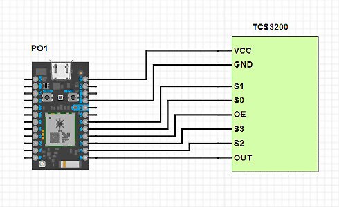
Scheme-It

TCS3200 Recap
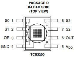
The TCS3200 is a simple IC that contains multiple photodiodes, which can detect red, green, blue, and white light. The sensor is commonly mounted onto a PCB with all needed passive components and multiple LEDs for lighting the target. When the term “TCS3200” is used, it typically refers to the module as a whole.

The output of the TCS3200 is a square wave whose frequency is directly proportional to the light intensity, and only one color can be read at any one time. The color that is desired is chosen using pins S2 and S3, and the possible combinations are shown in the table below.

The frequency of the output depends on not just the light intensity but the frequency setting that is selected using pins S0 and S1. The nominal maximum frequency is 600kHz (with the lowest being 12kHz), and the specific options for S0 and S1 are shown in the table below.

The output of the TCS3200 is gated with the OE pin, meaning this pin controls whether the TCS3200 can send data out or not (similar to a chip select). When this pin is low, the TCS3200 can output its signal from the chosen color, and if this pin is high, then the output is high impedance (which allows for other modules to use the same I/O line).
Coding the TCS3200
Unfortunately, not every sensor has a library, and this is an example! This means that any code written here is from scratch, so it is important to understand how it works. To use the sensor, we first need to set pins S0 and S1 to choose the frequency scaling. While the Photon is capable of measuring high-speed signals, the code seemed to struggle to operate at the 100% frequency setting. The best frequency setting to use for the Photon is the 20% setting, which means we need to set S0 high and S1 low.
    // TCS3200 Frequency
    digitalWrite(D4, HIGH);     // 20% frequency
    digitalWrite(D5, LOW);
In order to read data, we have to set OE to low, which enables the TCS3200. This is something that can be set in the setup() function and forgotten about.
// Enable TCS3200 output (active low)
    digitalWrite(D3, LOW);
Choosing the colors to read (red, green, and blue) is done by setting the pins S2 and S3, but it is tedious to write this code out in full every time you need a color change. Therefore, it is better to create a function that allows us to use a more readable code.
// S2 = 0 and S3 = 0
void sensor_red(void)
{
    digitalWrite(D2, LOW);
    digitalWrite(D3, LOW);
}

// S2 = 0 and S3 = 1
void sensor_blue(void)
{
    digitalWrite(D2, LOW);
    digitalWrite(D3, HIGH);
}

// S2 = 1 and S3 = 1
void sensor_green(void)
{
    digitalWrite(D2, HIGH);
    digitalWrite(D3, HIGH);
}
Reading the output of the TCS3200 is done by measuring the output frequency of the OUT pin. The easiest way to do this on platforms that use the standard Arduino library (such as the Photon and Uno) is to use the pulsein() function. This function will measure the time taken for a signal on an I/O pin to change state and return a number that is equal to the number of microseconds taken. Again, this operation is put into a function with an easy-to-remember name as shown below. The second parameter in the pulsein() function is whether we are measuring the time for high to low or low to high, but since the TCS3200 output has a duty cycle of 50%, it does not matter (therefore, HIGH is used).
float get_colorIntensity(void)
{
    return pulseIn(D0, HIGH);
}
Calibrating the Code
The output of the sensor is not easy to use, as ambient light can change, and light intensity varies considerably depending on your environment. The code requires calibration, therefore, before it is used. Before the main application is executed or programmed, the sensor needs to be mounted into its desired location, and from there, color cards should be scanned with their numbers printed to a terminal. Write these numbers down, as they represent the highest and lowest values for each color sensor. The easiest calibration method involves a piece of white card and a piece of black card as these measure the extremes for all colors at the same time. The code below can be used to dump the raw value from each color.
sensor_red();
Serial.print("R: " + String(get_colorIntensity()) + "  ");
sensor_green();
Serial.print("G: " + String(get_colorIntensity()) + "  ");
sensor_blue();
Serial.print("B: " + String(get_colorIntensity()) + "  ");
Serial.println();
With the max and minimum values obtained, these values need to be mapped to a range (preferably between 0 and 255). While this can be done arithmetically, we will instead use the Arduino map() function (which does it all automatically). This function maps the minimum and maximum values onto a linear scale and then scales this to a new scale.
// These are obtained experimentally
int rMax = 861;
int rMin = 15000;
int gMax = 15;
int gMin = 270;
int bMax = 17;
int bMin = 300;

// Get each color and convert it to a scale between 0 and 255
sensor_red();
redValue = map(int(get_colorIntensity()), rMin, rMax, 0, 255);
sensor_green();
greenValue = map(int(get_colorIntensity()), gMin, gMin, 0, 255);
sensor_blue();
blueValue = map(int(get_colorIntensity()), bMin, bMax, 0, 255);
A Working Example
// This #include statement was automatically added by the Particle IDE.
#include <math.h>
#include "Particle.h"

void sensor_red(void);
void sensor_green(void);
void sensor_blue(void);
float get_colorIntensity(void);

int rMax = 861;
int rMin = 15000;
int gMax = 15;
int gMin = 270;
int bMax = 17;
int bMin = 300;

void setup()
{
    Serial.begin(9600);

    // TCS3200 connections
    pinMode(D0, INPUT);         // OUT
    pinMode(D1, OUTPUT);        // S2
    pinMode(D2, OUTPUT);        // S3
    pinMode(D3, OUTPUT);        // OE
    pinMode(D4, OUTPUT);        // S0
    pinMode(D5, OUTPUT);        // S1

    // TCS3200 Frequency
    digitalWrite(D4, HIGH);     // 20% frequency
    digitalWrite(D5, LOW);

    // Enable TCS3200 output (active low)
    digitalWrite(D3, LOW);
}


void loop()
{
    // Get readings from TCS3200
    sensor_red();
    Serial.print("R: " + String(get_colorIntensity()) + "  ");
    sensor_green();
    Serial.print("G: " + String(get_colorIntensity()) + "  ");
    sensor_blue();
    Serial.print("B: " + String(get_colorIntensity()) + "  ");
    Serial.println();

    sensor_red();
    redValue = map(int(get_colorIntensity()), rMin, rMax, 0, 255);
    sensor_green();
    greenValue = map(int(get_colorIntensity()), gMin, gMin, 0, 255);
    sensor_blue();
    blueValue = map(int(get_colorIntensity()), bMin, bMax, 0, 255);

    delay(100);
}

// S2 = 0 and S3 = 0
void sensor_red(void)
{
    digitalWrite(D2, LOW);
    digitalWrite(D3, LOW);
}

// S2 = 0 and S3 = 1
void sensor_blue(void)
{
    digitalWrite(D2, LOW);
    digitalWrite(D3, HIGH);
}

// S2 = 1 and S3 = 1
void sensor_green(void)
{
    digitalWrite(D2, HIGH);
    digitalWrite(D3, HIGH);
}

// Get color frequency time (inversely proportional to color)
float get_colorIntensity(void)
{
    return pulseIn(D0, HIGH);
}

Have questions or comments? Continue the conversation on TechForum, DigiKey's online community and technical resource.
Visit TechForum


 中国
中国