Thermal Considerations for LED-Based Luminaires
投稿人:电子产品
2014-09-09
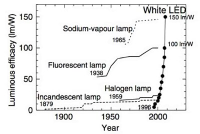
As the use of LED-based lighting fixtures (called luminaires in the lighting business) becomes more commonplace, their designers face the LED contradiction. While LEDs are far more efficient than incandescent bulbs (Figure 1), they have much lower maximum-allowed operating temperature, and are also much harder to keep below operating-temperature limits. [Note that the visible-light luminous efficacy of LEDs is approximately 100 lumen/W, compared to approximately 15 lumen/W for incandescent lamps.] Part of the difference in thermal ruggedness is due to the incandescent bulb’s construction of glass, metal, and ceramic, which can inherently tolerate more heat than a LED package..

Figure 1: The luminous efficacy of LEDs (often informally confused with their efficiency) has increased dramatically over the years and is now five times to six times better than incandescent bulbs; ironically, the thermal issues and associated dissipation challenges are far more difficult for LEDs.
However, a large part of this difference is due to how the LED manages its own heat compared to a traditional bulb. Thermal physics shows that there are three ways for heat to travel from its source to a cooler sink:
- Radiation, where the heat energy leaves as electromagnetic infrared waves. (Note that this is the only choice in the vacuum of space, making the cooling of spacecraft a real challenge.)
- Conduction, where the heat travels through a solid or static liquid.
- Convection, where the heat is carried away by a moving fluid (a gas, usually air, or a liquid in some advanced designs).
Thus, while the LED is much more efficient than the incandescent source, its thermal situation is much more difficult to manage, since ensuring a low-impedance thermal path and sufficiently cool outlet at the sink may be a problem. The greater the difference between source and sink, the better the overall thermal-removal cycle will function. Again, it is basic physics: without an active heat-pumping system such as a refrigerator, heat can flow only from a hotter area to a cooler one, and the amount of heat which can flow, and thus the rate of heat removal, is dependent on that differential.
Complicating the issue, the LED-based luminaire may also have to deal with the heat of its AC/DC power supply, while an AC-incandescent bulb does not have to deal with this source. Although a well-designed LED supply is usually relatively efficient at 80% or better, that still leaves some additional amount of heat to be factored into the thermal analysis.
Modeling the LED heat situation
The designer's objective is to keep the LED die’s junction temperature below a specified value, as called out by the LED manufacturer. This is usually a temperature between 85⁰C and 125⁰C, but may be lower if the vendor wants to claim a longer LED life, stable output intensity, or output-color stability, as heat is the primary cause of LED deterioration and even failure. Since the die temperature is not directly accessible for measurement, designers must use a model of the LED to infer the critical number based on external readings.
Vendors provide these models, which show the heat-flow path and the thermal impedance at each stage along the path. The path will include the LED die itself, internal bond wires, the die’s thermal path as mounted to the substrate or the LED package, the package itself, and contacts or leads (Figure 2). The model is analogous to a power-supply resistance and current-flow model, where there is a fixed-voltage source (the LED heat) which drives a string of resistors in series (thermal impedances). The challenge is to model all the resistances and then determine the resultant current flow — where the current flow is analogous to the heat flow.

Figure 2: A simplified, but still insightful, LED-thermal model, where Q is heat flowing from hot to cold through the LED; Tj is the temperature at the junction of the device; Tc is the temperature at the case of the LED array; Th is the temperature at the point where the heatsink is attached to the LED array; Tamb is the ambient-air temperature; Rθjc is the thermal resistance from junction to case of the LED array; Rθch is the thermal resistance between the case of the LED array and the heatsink; Rθha is the thermal resistance of the heatsink.
Modeling heat flow and cooling is more complicated than modeling power sources, resistors, and current, because the heat is not confined to well-defined, restricted pathways of wires and components. Heat conducts in all directions through solids and static liquids, and is conveyed in often complex ways by the convection flow. For these reasons, a full modeling of an LED source or luminaire begins with basic analysis of thermal impedances, but often must extend to using a computational fluid dynamics (CFD) modeling package to more thoroughly analyze the more complex heat-flow paths and resultant temperatures at key points. The two key questions in any cooling situation are simple to state, although their answers may not be simple to provide. These are: 1) to where is the heat ultimately being removed; and 2) how is it getting there? There is no point in removing heat from a source if it has nowhere to go at the other end, as it will eventually stop going there. It is like a car that can take multiple roads and highways between starting-point A and end-point B; if there is a tie-up or traffic jam as you approach B, eventually the car will make no progress.
Cooling approaches
In most thermal situations, designers have a choice between passive or active cooling. The passive cooling uses natural conduction and associated convection, perhaps supplemented by a heatsink to accelerate both, while active cooling usually employs a fan to drive the airflow (although other techniques such as fluid flow, are used in some niche applications such as server data-center cooling). In general, designers usually begin with consideration of passive cooling when possible, for several reasons. It’s quiet, reliable (no fan to wear out), and inexpensive (no fan or controller needed). However, in some situations, passive alone may not be an acceptable choice, as it may provide insufficient cooling; what’s more the needed heatsink may be too large, unsightly, mechanically unwieldy, or costly. In general, a fan-based active system of equal cooling capacity is smaller than a passive-only design with heatsink, although the active design will still need a heatsink to conduct heat away from the LED itself before this heat can be removed.
Just as in the cooling of power supplies and hot chassis with a fan-driven air flow, there are secondary problems with both passive and active designs. In luminaires, accumulation of common dust is the concern. Dust, which is generally inevitable and unavoidable even in residences with good air filtering, will settle on the cooling fins of a heatsink or on fan blades, thus reducing their efficiency and cooling capacity below the design minimum. Filters are not practical in luminaires and they, too, would eventually need cleaning.
Another factor is the passive versus active approach trade-off in user expectations regarding luminaire acoustic noise. Even though the fans are extremely quiet (often well below 50 dB) there will be some noise from the fan as well as airflow through the heatsink itself. Users may be used to and expecting an absolutely silent light source, and be unnerved or uncomfortable with even this very modest hum and airflow noise.
There’s an electrical issue, as well. Just as the cooling fan in a car or PC may need to keep running after the unit is shut off to bring the temperature down, the luminaire’s cooling fan may need to run for a few minutes after shut-off to remove the residual LED heat. Unlike the smart- or soft-power control in a car or PC, a lamp’s fixture-wiring circuit is usually a direct-connect on/off loop: when the user turns the lamp “off,” power is removed and there is no way to run a cooling fan. Thus, an active system must be sized to remove heat quickly enough during normal operations so that no power-off fan time is needed.
Vendors address the complex issues
Designers who plan to use heatsinks alone or heatsinks plus fans for cooling can consider either standard off-the-shelf hardware or custom-designed units. While the latter may be a better solution technically, they are more costly than standard units (except perhaps in very, very high volumes) and have longer lead times; also, until a prototype is built and evaluated, the actual performance may differ from the modeled results, or there may be unforeseen mechanical problems.
In contrast, a standard unit may not be the absolute best, but is available, less costly, and samples are available to check and verify before the design is made final or larger quantities are ordered. Further, vendors of heatsinks and fans recognize that cooling LED-based bulbs and luminaires is a large and growing market, and so they have developed many standard versions and variations for designers to consider.
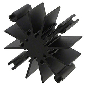
For passive-thermal management, Wakefield Thermal Solutions offers the 882-100AB series of radial-fin heatsinks (Figure 3). It is specifically designed for natural convection for LEDs arranged in a “star” configuration, which is a common style. Each member of the family features multiple sets of mounting holes to accommodate different LED body sizes, which simplifies design-in and inventory stocking. The thinnest version has a height of 0.5 inch (12.7 mm), and will keep the temperature rise above ambient to 60⁰C with a 9 W-dissipation load; the tallest member is 3.0 inches (76 mm) high and holds temperature rise to 28⁰C with the same load. The design can also be fitted with a fan, which greatly increases the thermal capabilities.

Figure 3: The 882-100AB series of radial-fin heatsinks from Wakefield Thermal Solutions is designed for multi-LED star-array configurations available from several vendors, and can accommodate different LED diameters; it can also be fitted with a fan in case active cooling is needed.
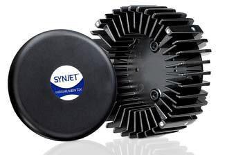
Designed specifically for active cooling of LED modules and arrays, the SynJet Downlight Cooler from Nuventix claims a 100,000 hour life (Figure 4). It can be hardwired for operation in one of four active modes — high-performance, standard, silent, and 100% duty-cycle PWM — with associated sound-pressure level (SPL) ratings of 30, 22, 19, and 30 dB, as well as used as a passive-only unit which is silent.. Depending on mode, the 5 V SynJet itself requires between 350 and 450 mW. It is specified in terms of the LED power it can dissipate while keeping temperature rise to 30⁰C; for the five modes cited, the dissipation ratings are 40, 32, 28, 32, and 15 W, respectively — a wide span, as you would expect given the differences between modes.
The Synjet Cooler is mounted to a heatsink, creating a thermal-management solution. The unit is a plastic housing surrounding an oscillating diaphragm. The diaphragm and housing create pulses of high-velocity turbulent air flow, which pull air in its wake, increasing the overall air flow by as much as five times, according to the supplier, and improving heat transfer out of the heatsink. Engineers can find additional details on Synjet Coolers in a Product Training Module from Nuventix entitled Synjet Coolers for use in LED lighting.

Figure 4: For designs which will be using active cooling, the SynJet Downlight Cooler 120 from Nuventix integrates the fan and the heatsink, and can be set to operate in multiple modes, each of which offers different cooling capacity, noise level, and other performance trade-offs.
In summary
While LEDs seem to be the near-ideal lighting alternative to inefficient incandescent bulbs due to their efficiency, small size, and versatility, the reality is that thermal issues can consume a great deal of a designer’s time and thinking. As a semiconductor device, heat is the enemy with respect to outright failure, intensity fading, color shifts, and consistency of performance. LED-based lighting and fixtures (luminaires) present a design opportunity but also a challenge, compared to traditional incandescent-bulb units. While LEDs are much more efficient, and thus dissipate much less heat than bulbs, the heat they do generate remains in the die and does not radiate away as it does with a bulb. Unless that heat is removed, the LED’s life will be shortened and the LED may even self-destruct.
Providing the proper thermal-management system requires consideration of physical configuration, number of LEDs, mounting technique, choice of passive-versus- active cooling, thermal modeling, and appropriate heat-sinking trade-offs. This article has looked at the basic model of LED-heat transfer, and how heat can be removed versus the LED-power level. It focused on trade-offs between passive-and-active cooling techniques used with luminaires, and discussed why the choice is both a technical one and one that must consider major end-user considerations.
For more information on the parts mentioned in this article, use the links provided to access product information pages on the DigiKey website.
免责声明:各个作者和/或论坛参与者在本网站发表的观点、看法和意见不代表 DigiKey 的观点、看法和意见,也不代表 DigiKey 官方政策。


 中国
中国