Sorting Through Proximity and Distance Sensor Technology Choices

作者:Jeff Shepard

投稿人:DigiKey 北美编辑

Using proximity and distance sensors to detect the presence and location of items without physical contact can be an important aspect of controlling industrial processes like material handling, agricultural machinery, fabrication and assembly operations, and food, beverage, and pharmaceuticals packaging.

These sensors are available using a variety of technologies including photoelectric, laser, inductive, capacitive, magnetic, and ultrasonic. When determining the best choice for a given application, factors like range, size, accuracy, sensitivity, resolution, and cost need to be considered.

A key factor in many applications is the material of the object to be detected. Some sensors behave differently with hard versus fibrous surfaces, and other sensors can be affected by the color or reflectivity of the object.

This article reviews commonly available non-contact proximity sensor technologies, looking at how they work, their basic performance characteristics and exemplary sensors from SICK, along with some intended applications.

Photoelectric sensors

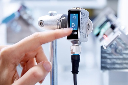
Photoelectric sensors, like the W10 photoelectric proximity sensors from SICK, are simple to use and install and are available with a range of features suited for numerous applications. The sturdy design of the W10 sensors makes them suitable for precise object detection in challenging environments. The integrated touchscreen speeds parameter setting and sensor deployment (Figure 1).

Image of touchscreen on SICK photoelectric sensorsFigure 1: The touchscreen on these photoelectric sensors can speed commissioning and deployment. (Image source: SICK)

Available teach-ins enable designers to adapt these sensors to specific application requirements. In addition, integrated functions like speed settings, standard and precision measurement modes, and foreground and background suppression mean a single sensor can be used in an array of applications. The sensor series includes four variants, which differ in their operating distances and mounting options.

Background suppression

Photoelectric proximity sensors with background suppression (BGS) use triangulation between the sending and the receiving elements. Signals from objects behind the set sensing range are suppressed. In addition, SICK’s BGS technology ignores highly reflective objects in the background and can handle difficult ambient lighting conditions.

Background suppression is especially useful when the target object and the background (like a conveyor belt) have similar reflectivity or if the background reflectivity is variable and can cause interference with detection.

Foreground suppression

Photoelectric proximity sensors with foreground suppression (FGS) can detect objects at a defined distance. All objects between the sensor and the sensing distance (set to the background) are detected. To ensure reliable sensing, the background needs to be relatively bright and should not vary in height.

When objects are on a reflective surface like a white or light-colored conveyor belt, foreground suppression can improve detection. Rather than detecting light reflecting from the object, the sensor detects the object by the absence of the light reflected by the conveyor belt.

Retro-reflective

In a retro-reflective sensor, the emitted light hits a reflector, and the reflected light is evaluated by the sensor. Errors can be minimized by using polarizing filters. Stretch films and plastic wrappings that are transparent can interfere with these sensors. Reducing sensor sensitivity can help overcome those challenges. In addition, the replacement of standard IR light emitters with lasers can enable longer sensing ranges and higher resolution.

Retro-reflective sensor performance can be improved using a lower-than-normal switching hysteresis. In these designs, even minimal light attenuation between the sensor and reflector, for example, caused by glass bottles, can be reliably detected. SICK also offers a monitoring system called AutoAdapt that continuously regulates and adapts the switching threshold in response to the gradual buildup of contamination that could lead to failure of the sensing system.

Through-beam

In contrast with retro-reflective sensors, through-beam sensors use two active devices: a sender and a receiver. Through-beam sensing enables longer sensing ranges. The replacement of IR emitters with laser diodes can further enhance sensing distance while maintaining high resolution and precise sensing.

Fiber-optic

Fiber-optic sensors are a variation on through-beam designs. In a fiber-optic photoelectric sensor, the sender and receiver are copackaged in a single housing. Separate fiber optic cables are used by the sender and receiver. These sensors are especially suited for use in high-temperature applications and in hazardous and harsh environments.

Photoelectric sensor arrays

The RAY26 Reflex Array family of photoelectric sensors like the model 1221950 enable reliable object detection of flat objects as well as fast commissioning. When combined with a reflector, the photoelectric sensors also detect small, flat, transparent, or uneven objects as small as 3 mm. Within a 55 mm-high uniform light array, the sensors detect the leading edge of the object. This means that even perforated objects can be reliably detected without complex switching (Figure 4).

Image of photoelectric sensor arrays can detect objects as small as 3 mmFigure 2: Photoelectric sensor arrays can detect objects as small as 3 mm in a 55 mm high field. (Image source: SICK)

Laser distance sensors

Designers of applications like level monitoring in storage containers, position detection of objects on conveyors, XY position of the axis in automated forklift systems, vertical positioning of cranes in warehouses and overhead conveyors, and diameter monitoring during coil winding can turn to the DT50 Laser Distance Sensors. These sensors support time of flight (ToF) distance measurements up to several meters using reflected laser light to provide immunity to ambient lighting, and precise and reliable operation.

For example, the DT50-2B215252 has a range of 200 to 30,000 mm and several special features, including:

  • Rugged housing with an enclosure rating of IP65 and IP67
  • Can provide up to 3,000 distance measurements per second
  • Minimum response time of 0.83 ms
  • Compact housing supports a range of applications from industrial robots to measuring fill heights of storage containers

High-res measurements using statistics

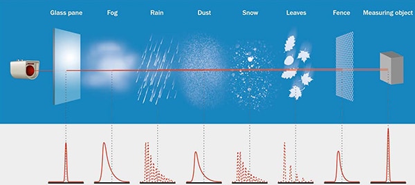
High-definition distance measurement plus (HDDM+) is a high-resolution ToF measurement technology that can be used in laser distance and light detection and ranging (LiDAR) sensors. In contrast with single-pulse or phase correlation sensing technologies, HDDM+ is a statistical measurement process.

The sensor software statistically evaluates the echoes of multiple laser pulses to filter out interference from sources like panes of glass, fog, rain, dust, snow, leaves, fences, and other objects to calculate the distance to the intended target. The resulting distance measurement can have a high level of certainty even under challenging ambient conditions (Figure 5).

Diagram of SICK HDDM+ software (click to enlarge)Figure 3: SICK’s HDDM+ software uses a statistical evaluation process to eliminate “noise” from items like glass panes, fog, rain, dust, snow, leaves, and fences. (Image source: SICK)

Typical applications for HDDM+ technology include distance measurement for quality control in electronics production, LiDAR multi-dimensional object detection and position determination in mechanical and plant engineering, and determining the position of industrial cranes or vehicles.

The sensing range of HDDM+ sensors is up to 1.5 km on retro-reflective tape. For example, model DT1000-S11101 has a range up to 460 m with a typical measurement accuracy of ±15 mm for natural objects and an adjustable resolution from 0.001 to 100 mm.

Inductive

Inductive proximity sensors like the IME series from SICK can detect ferrous and non-ferrous metal objects. These sensors consist of an inductor-capacitor (LC) resonant circuit that generates a high-frequency alternating electromagnetic field. The field is dampened when a metallic object enters the detection range. The dampening is detected by the signal evaluation circuit and an amplifier that produces the output signal (Figure 4).

Diagram of basic inductive proximity sensorFigure 4: A basic inductive proximity sensor consists of an LC circuit that produces an alternating field, a signal evaluator, and an amplifier. (Image source: SICK)

Two important specifications for the sensing distance of several proximity sensor technologies are the nominal sensing distance (Sn) and the secured sensing distance (Sa). Sn does not consider manufacturing tolerances or external influences like operating temperature. Sa takes into consideration both manufacturing tolerances and variations in operating conditions. Sa is typically about 81% of the value of Sn. For example, for the model IME08-02BPSZT0S inductive sensor, Sn is 2 mm and Sa is 1.62 mm.

Capacitive sensing

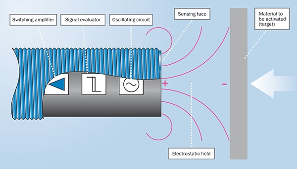
Like inductive sensors, capacitive proximity sensors use an oscillator. In this case, an open capacitor is used where the active electrode in the sensor produces an electrostatic field relative to ground. These sensors can detect the presence of a wide range of materials including metallic and non-metallic objects.

When an object enters the electrostatic field, the amplitude of the oscillations in the resonant circuit change based on the dielectric properties of the material. The signal evaluator detects the change, and an amplifier produces the output signal (Figure 5).

Diagram of oscillating circuit produces an electrostatic fieldFigure 5: In a capacitive proximity sensor, an oscillating circuit produces an electrostatic field that changes characteristics when the target to be sensed enters the field. (Image source: SICK)

Like inductive proximity sensors, there are several specifications related to the sensing distance of capacitive proximity sensors including Sn, Sa, and a reduction factor. For example, the model CM12-08EBP-KC1 has an Sn of 8 mm and a nominal Sa of 5.76 mm.

The object to be sensed must be at least as large as the sensor face and the sensing distance varies with the reduction factor of the material. Reduction factors are related to the dielectric constant of the material and can vary from 1 for metals and water to 0.4 for polyvinyl chloride (PVC), 0.6 for glass and 0.5 for ceramics.

Magnetic

Magnetic proximity sensors respond to the presence of a magnet. Magnetic proximity sensors from SICK use two detection technologies:

  • Giant magneto resistive (GMR) sensors are based on resistors that change their value in the presence of a magnetic field. A Wheatstone bridge is used to detect the change in resistance and produce an output signal. The MZT7 cylinder sensors, like the MZT7-03VPS-KP0 designed for use with T-slot cylinders, use GMR technology to detect piston positioning in pneumatic drives and in similar applications.
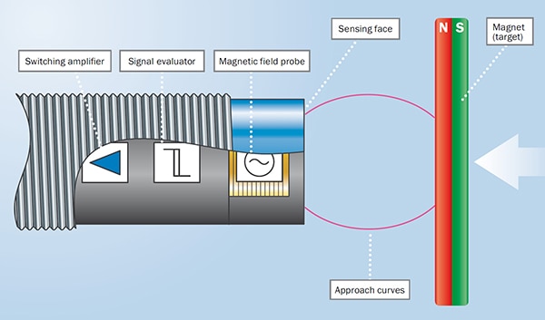
  • LC technology uses a resonant circuit that resonates with a small amplitude. If an external magnetic field approaches, the resonant amplitude increases. The increase is detected by a signal evaluator and an amplifier produces the output signal (Figure 6). The MM08-60APO-ZUA has an Sn of 60 mm and an Sa of 48.6 mm.

Image of the field probe can use GMR or LC technologyFigure 6: In a magnetic proximity sensor, the field probe can use GMR or LC technology. (Image source: SICK)

Ultrasonic sensors

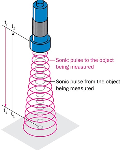
For objects up to 8 m away, designers can turn to ultrasonic sensors like the UM30 family from SICK. These sensors have integrated temperature compensation to improve measurement accuracy and provide color-independent object detection, immunity to dust, and operation up to +70°C. They measure distances based on time-of-flight technology where the distance is equal to the speed of sound multiplied by the total acoustic time of flight (t2) with the total divided by 2 (Figure 6).

Diagram of ultrasonic sensors can measure distanceFigure 7: Ultrasonic sensors can measure distance based on the total time of flight (t2) of the sound waves. (Image source: SICK)

Ultrasonic sensors like model UM30-212111 are suited for applications like empty tote monitoring. An internal temperature monitor produces a measurement accuracy of ±1%. These color-independent sensors can detect hard to distinguish objects even in the presence of dirt and dust.

Conclusion

The good news is that there’s a wide range of proximity and distance sensor technology choices. That means there’s a solution for every application requirement. The challenge is sorting through the many choices and finding the optimal solution for detection of specific materials under actual application and operating conditions.

免责声明:各个作者和/或论坛参与者在本网站发表的观点、看法和意见不代表 DigiKey 的观点、看法和意见,也不代表 DigiKey 官方政策。

关于此作者

Jeff Shepard

Jeff 从事电力电子、电子元件和其它技术主题写作 30 余载。在其于 EETimes 任职高级编辑期间,他开始了电力电子写作。后来,他创立了一份叫《Powertechniques》的电力电子杂志,再后来又创立了一家全球性的研究和出版公司 Darnell Group。在开展各项业务的同时,Darnell Group 还发布了 PowerPulse.net,专门针对全球电力电子工程社区提供每日新闻。他是一本名为《Power Supplies》的开关模式电源教课书的作者,该书由 Prentice Hall 旗下 Reston 分部出版。

Jeff 还是 Jeta Power Systems 共同创始人,这是一家高功率开关电源制造商,后来被 Computer Products 收购。Jeff 也是一个发明家,其名下拥有 17 项热能收集和光学超材料美国专利,同时他也是掌握电力电子行业全球趋势的专家和网红发言人。他拥有加利福尼亚大学定量方法和数学硕士学位。

关于此出版商

DigiKey 北美编辑