RF Power Measurement Using RMS Detectors
投稿人:电子产品
2014-02-20
In most circuits for wireless applications, it is necessary to monitor and control both the transmitted and received levels of RF power. This is done to minimize power amplifier (PA) current consumption, control receiver gain, optimize performance and efficiency, and meet signal-strength regulatory mandates.
To measure RF power, three different approaches are used: the peak detector/amplifier, the logarithmic (log) amplifier, and the RMS converter. Each of these meets the application priorities and needs of the different types of complex RF waveforms, as well as the performance and cost issues.
Note that RF power measurement can be done in two venues: wireless and wired. For wireless, the actual radiated power is sensed by a transducer such as a diode target, which then produces a signal proportional to the RF power which impinges on it. This is a true "RF power" measurement.
In contrast, when we measure RF power in a wired circuit, we are not really measuring the power directly. Instead, we are determining the RF power by measuring an "analog" of it, in this case, the voltage across or current through a known resistor. Once you know voltage or current and the resistance, you can compute the power. While this is an indirect way to assess RF power, it is quite accurate if done properly, and certainly more convenient and practical.
It may seem that the obvious way to compute the power is to digitize the sensed RF voltage or current and then perform appropriate calculations, but this is very impractical for several reasons. The digitization process would require a converter with extraordinarily-high speed and resolution, which is generally not available. Such a converter would also dissipate significant power, while the high-speed, real-time calculation would require considerable processing capacity.
As a result, RF power measurement is done in the analog domain, with very rare exceptions. The output of the power-measurement block is an analog signal which is related in some way to the RF power attribute of interest. If necessary, this signal can be digitized if needed, since it is a much slower signal than the RF waveform itself (for this reason, RMS power detectors are sometimes called RMS/DC converters).
Also note that some RF power-measurement subsystems use the term "video" instead of "RF". This is a holdover from the past, when wideband signals where primarily used for video applications. The video adjective is still used in some legacy products and literature.
Power measurement techniques and applications
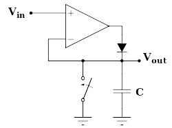
The peak or envelope detector uses an op amp, diode, and capacitor to capture and hold the peak value of the input RF signal. The signal charges the capacitor through the op amp, and the diode prevents discharge of the capacitor (Figure 1). As the name says, this topology is useful when the peak or maximum RF signal value is needed but it is not useful for determining average or any other sort of nonpeak value.

Figure 1: In the classic peak detector, a capacitor retains the peak voltage level of the signal, and a switch is used for resetting the detected level; the switch is usually implemented electronically.
The log amplifier or log detector also uses a diode, but in a very different topology than the peak detector. It is based on the inherent logarithmic response of a diode, which develops a voltage output proportional to the logarithm of the input (Figure 2); therefore, it is linear in output versus dB input. It is widely used and is especially useful when the magnitude of RF signal of interest spans decades, which is a common situation: range of 100 dB is not unusual. The log amp is a good fit for pulsed signals, such as radar, because of its fast response and match with the application priorities.

Figure 2: The log amplifier makes use of the inherent current/voltage transfer function of a diode (IS and VT are the saturation current and the thermal voltage, respectively, of the diode).
The RMS detector (also called an RMS converter or RMS/DC converter) is well-suited to signals with high crest factors (crest factor is the ratio of the peak to RMS value of the signal). High crest factors, as much as 10 to 15 dB, are now becoming more common with the increased implementation of advanced modulation techniques such as higher-order QAM (quadrature amplitude modulation) used for CDMA (carrier detect, multiple access), and OFDM (orthogonal frequency-division multiplexing) for WiMax. The RMS approach implements what is called "implicit analog computation" by combining an analog multiplier and an op amp (Figure 3). [Note that a similar implicit-computation approach is used for measurement of 50/60 Hz AC power.]

Figure 3: By combining an analog multiplier with an op amp, this circuit performs an implicit RMS-to-DC conversion in real time, without a digital conversion or calculation.
Which RF detector is best? It depends on the application, of course, and large, complex, sophisticated systems such as high-performance radar, mil/aero, or even SDR (software-defined radio) designs may use multiple different RF power detectors in their signal chain. However, due to the signal formats and performance demands of newer applications such as smartphones and the electronic control of fiber-optic links, as well as technology and process advances, the RMS detector is getting more attention from vendors.
Key RF-power performance parameters include maximum operating frequency, dynamic range, and for log detectors, response time. Also critical to all three RF detector types is temperature drift, due to the inherent physics of their constituent components such as their diodes, which have well-known temperature coefficients. Modern RF detectors use a variety of internal compensation schemes to achieve drift as low as ±0.5 to ±1.0 dB over their full operating range.
IC vendors taking on modules
As IC processes improve, single-chip RMS converters are challenging even the smallest modular products. The latter group provides the best performance, but at size, weight, power, and cost penalty. For many applications, the IC solution has more than sufficient performance, while their well-known virtues outweigh whatever shortcomings the IC may have.
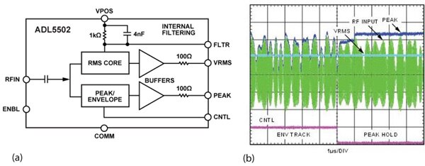
Analog Devices offers the ADL5502 true-RMS power detector high-frequency receiver and transmitter signal chains from 450 MHz to 6 GHz with envelope bandwidths over 10 MHz (Figure 4a). As an added benefit, this device also includes an envelope (peak) detector which allows the determination of the crest factor of a modulated signal, when used in conjunction with the RMS function (Figure 4b). It can be used for crest-factor measurements of both simple and complex waveforms, but is particularly effective at measuring signals with high crest factors (high peak-to-RMS ratio) such as W-CDMA, CDMA2000, and QPSK-/QAM-based OFDM waveforms. The IC is available as a tiny 8-bump, 1.5 x 1.5 mm wafer-level chip-scale device.

Figure 4: (a) Left, Analog Device's ADL5502 RMS/DC converter operates to 6 GHz, meeting the needs of the latest RF bands, and also includes a peak detector; (b) right, the IC lets the system simultaneously determine the RMS value of the complex RF signal and also the peak; both are needed for some specialized measurement/control functions.
The LTC5587 from Linear Technology Corp. is a 10 MHz to 6 GHz RMS power detector with an integrated 12-bit serial analog-to-digital converter (ADC) which can accurately measure the RF power of modulated signals with crest factor as high as 12 dB, over a detection range from -34 to +6 dBm (Figure 5). It then provides a 12-bit serial digital output of the detector value that is directly proportional to the RF signal power measured in dBm. It is suitable for precision power measurement for a wide variety of RF standards, including LTE, WiMAX, W-CDMA, TD-SCDMA, CDMA, CDMA2000, EDGE, and GSM, among others. It is also small, housed in a 3 x 3 mm, 12-lead DFN package, and well-suited for picocell, femtocell, and similar RF power-control situations. Output variation versus temperature is ±0.5 dB from –27 to –10 dBm and ±1.0 dB from –4 to +6 dBm.

Figure 5: The LTC5587 from Linear Technology Corp. also reaches 6 GHz, but has a lower range of 10 MHz; it also includes a 12-bit ADC and interface for providing digitized results of the analog RMS/DC conversion.
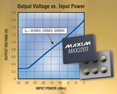
Maxim's MAX2203 (Figure 6) is an even-smaller RMS power detector, in a 6-bump wafer-level package (WLP). It operates from 800 MHz to 2.0 GHz, and accepts an RF signal at the input, and outputs the same voltage regardless of the peak-average of the input signal. The output voltage and input power is linear in dB. The device has a –25 to +3 dBm detection range, and every dB change in input power gives a 40 mV typical change in output voltage. It specifies RMS accuracy of 0.1 dB (typical) from WCDMA modulation change and ±0.5 dB detection error due to temperature.

Figure 6: Maxim's MAX2203 is offered in a 6-bump wafer-level package and has a –25 to +3 dBm detection range, with 40 mV/dB scaling between input power and output voltage, along with RMS accuracy of 0.1 dB (typical) for WCDMA modulation.
The HMC1030LP5E DC to 3.9 GHz dual-RMS detector from Hittite Microwave Corporation (Figure 7), offers two identical channels in a single 32-lead, 5 x 5 mm surface-mount package. This makes it a good fit for I/Q (in-phase/quadrature) designs, or for measuring gain in a circuit using one detector at the input to a stage and the other at the output. It measures crest factor and envelope-to-average power ratio. Its specifications include input dynamic range of –55 to +15 dBm (70 dB dynamic range) and ±1 dB detection accuracy to 3.9 GHz.

Figure 7: The dual channels of the HMC1030LP5E RMS detector from Hittite Microwave simplify both quadrature-channel (I/Q) designs as well as comparative power in/out measurement requirements.
Summary
In most circuits for wireless applications, it is necessary to monitor both the transmitted and received RF power levels for optimum performance and efficiency, and to meet regulatory requirements. This can be done using power-detection components which implement very different approaches: the logarithmic (log) detector/amplifier, the peak detector, and the RMS (root mean square) detector.
This article briefly explained the RF and waveform situations for which each detector is a better fit, and then focused on the RMS detector approach. It also discussed requirements, especially for the latest wireless applications, and some specific products.
For more information on the parts mentioned in this article, use the links provided to access product information pages on the DigiKey website.
免责声明:各个作者和/或论坛参与者在本网站发表的观点、看法和意见不代表 DigiKey 的观点、看法和意见,也不代表 DigiKey 官方政策。


 中国
中国