RF Attenuators: For When You Have Too Much of a Good Thing
投稿人:电子产品
2015-09-10
Higher signal levels are generally a good thing in RF circuits. They result in increased signal-to-noise ratio (SNR) and reduce the problems caused by both internal circuit-component noise as well as external-signal noise. As a result, higher signal levels generally simplify many challenges of RF-circuit design.
However, in many systems, the RF signal can unavoidably have wide dynamic range spanning 30, 40, or more dB; some designs must deal with signals having a range of over 100 dB. Examples include radar or long-range wireless, or even short-range LANs where one or both of the link nodes are moving and there are obstacles and interference.
If a system is designed to function properly with lower-level signals, it may not have the headroom for the higher-power signals (in RF, power and signal level are usually closely correlated). The result is overload, saturation, and even possible damage to sensitive analog components such as front-end amplifiers. Even if there is no permanent damage, the system cannot function properly as long as elements of the signal chain are “maxed out.” In these cases, it may take a relatively long time for the components to come out of saturation so that the signal chain is once again viable. In other cases, the attenuator matches the maximum value of a signal at one point to the more-limited maximum of another stage in the chain.
For these reasons, it’s often necessary to manage and attenuate the signal level by a known or controllable amount, and that’s where RF attenuators play a role. There are three types of RF attenuators:
1) Fixed-value attenuators, providing values such as one or two dB, or 10 dB, 20 dB, or more dB.
2) Voltage-variable or voltage-controlled attenuators, where an analog voltage sets the attenuation level over a continuously variable range, such as between 0 dB and 30 dB or 0 dB and 60 dB.
3) The digitally controlled attenuator or digital-step attenuator (DSA), where a multibit code establishes the attenuation in discrete steps over a range of 0 dB to 32 or 64 dB, for example, in steps of one or two dB/bit; some products offer step sizes as small as 0.25 dB.
(Note that there are also mechanically-controlled attenuators, where the user sets the attenuation with a rotary knob. These are used almost exclusively in test situations or high-power one-off designs.)
The controllable attenuator is the complement of the variable-gain amplifier (VGA), which boosts a signal to match the range of components in the chain. For designs which need additional flexibility, there are even VGAs available which span both gain and attenuation such as from -10 to +40 dB; internally, these are built from a variable attenuator (voltage- or digital-control) in series with a gain block.
It may seem reasonable to simply use a variable attenuator instead of a fixed one, to provide maximum flexibility in use. However, this flexibility comes at a price, as variable attenuators are more costly, dissipate more power, and require (in most versions) a control signal at power-up, as well as continuous supervisory management while in use. Those are an additional burden on the system processor and initialization procedure. In contrast, there is nothing to do with a fixed attenuator, other than install it. In other cases, a “fixed” attenuator is designed to offer a controlled temperature coefficient, to be used to stabilize a high-power RF amplifier as its operating temperature changes.
Key attenuator parameters guide selection
As with all components, attenuators have many design specifications which define their suitability in a given application. The primary ones for attenuators are frequency range and attenuation value.
Some attenuators are designed and specified for relatively broadband use such as from 1 to 4 GHz, while others target narrowband situations such as the nominal 2.4 GHz ISM band. Although wider bandwidth may seem to be a benefit, it is more difficult to design and costly to achieve performance over a wider band. A comparable situation exists for variable attenuators. A wide-range unit which functions over a range of 60 or more dB is more costly than one which must do so over a more limited range of 30 dB.
The two parameters of frequency range and attenuation combine for other critical specifications: attenuation deviation or flatness across the frequency range, and across operating temperature. Flatness is typically on the order of 0.25 dB or 0.5 dB and is generally harder to maintain at higher frequencies.
If the attenuator is a fixed-value unit, the flatness needs to be specified only at that single dB value. However, for variable attenuators, the flatness may vary with the amount of attenuation, so its variations must be specified at different attenuation values, such as every 5 or 10 dB. Finally, as with nearly all passive and active components, performance must be specified at nominal temperature (25⁰C) as well as the device’s rated low and high temperatures; some vendors offer temperature coefficient data as well.
Power-handling capacity for attenuators ranges from milliwatts to thousands of watts. The power rating is one factor which determines the possible package, which can be a tiny surface-mount technology (SMT) device to larger coaxial and even waveguide packages, as power levels go to upper levels. Regardless of package type, most vendors specify power ratings for both continuous-wave (CW) operation as well as peak value for pulsed operation. Depending on the duty cycle of the pulse rating used, the ratio between CW- and peak-power ratings can be a factor of ×10, ×100, or more.
Of course, as with all RF components, the impedance of the attenuator should match the circuit. Most attenuators are designed for 50 Ω operation; some specialized ones are available for other values such as 75 Ω. If the circuit does not have a matching value, an impedance-matching circuit may be needed.
Also note that passive attenuators have a quasi-static insertion loss of typically between 3 and 5 dB. This must be taken into account in signal-level and attenuation analysis, and it may change by one or two dB over the frequency range. Vendors usually show the specific dB values of this loss in detail in the data sheet.
User choices offer options
Much of the growth in attenuator use has been in high-volume handheld devices such as smartphones, LAN nodes, or base stations, where power levels are relatively low, SMT packages are practical, and duty cycles are such that the peak/CW rating ratio is relatively small. Several standard devices illustrate the diversity of available small-signal, SMT attenuators (there are also larger, non-PC board attenuators with coaxial connectors intended primarily for use in-line with test setups).
The Avago AMMP-6640 is a DC-40 GHz variable attenuator which operates over a 20 dB range, with 5 dB insertion loss (Figure 1). This 5.0 × 5.0 × 2 mm GaAs device is specially designed for broadband operation, and uses two 0 to 1.2 VDC analog-control signals in tandem to set the attenuation level, (Figure 2). It targets Microwave Radio Systems and Satellite VSAT (very-small-aperture terminals) or DBS (direct-broadcast satellite) up/down Links. Due to its broadband nature, the vendor provides a detailed table of scattering parameters (s-parameters) S11, S21, S12, and S22 in 1 GHz steps from near zero to 40 GHz.
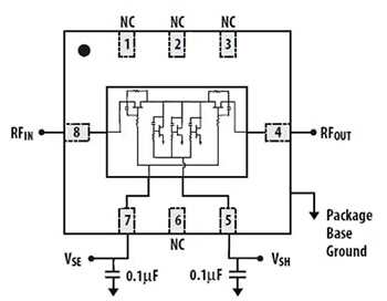
Figure 1: The Avago AMMP-6640 DC to 40 GHz variable attenuator uses tandem pairing of a series FET and a shunt FET to manage signal strength.
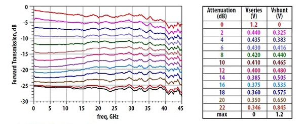
Figure 2: Attenuation for the Avago AMMP-6640 is controlled by two independent voltages, designated Vseries and Vshunt; the resultant attenuation is shown by the table entries.
For digital control, the SKY12343-364LF from Skyworks Solutions is a GaAs broadband seven-bit DSA for the 0.01 to 4.0 GHz band, with an attenuation range of 31.75 dB and 0.25 dB resolution (Figure 3). The programming logic levels of this single supply IC (+3.3 or +5 V) are TTL/CMOS-compatible with both a dual-mode serial controller and an integrated Serial Peripheral Interface (SPI) controller. It is designed for a wide variety of 3G- and 4G-cellular infrastructure applications. The graph of its attenuation error versus attenuation setting shows performance of better than ±0.5 dB at frequencies from 200 MHz to 4 GHz, and settings between 0 and 32 dB (Figure 4).
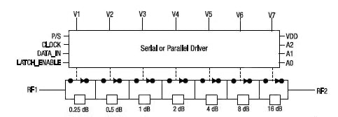
Figure 3: The SKY12343-364LF from Skyworks Solutions offers both a dual-mode serial controller and an integrated Serial Peripheral Interface (SPI) controller interface, and provides an attenuation range of 31.75 dB and 0.25 dB resolution from 0.01 to 4.0 GHz.
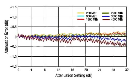
Figure 4: The graph of the attenuation error versus attenuation setting for the SKY12343-364LF shows that it varies only slightly across both variables, staying within a 1 dB window.
Another DSA is the PE4302 from Peregrine Semiconductor, a 6-bit, 31.25 dB, DC to 4 GHz unit, with 0.5 dB steps. In addition to its serial and parallel CMOS interfaces (Figure 5), this 3 V IC has a unique control interface that allows the user to preset the attenuation value at power-up. Its attenuation at major steps (Figure 6a) and attenuation error versus frequency (Figure 6b) are just a few of the many performance graphs the vendor provides.

Figure 5: With the Peregrine Semiconductor PE4302 DSA, the initial attenuation setting on power-up can be established in advance.

Figure 6: (a, top) The PE4302 DSA attenuation shows excellent flatness at all attenuation values and frequencies, with some deviation at maximum attenuation and frequency; (b, bottom) another way of looking at performance is the attenuation error versus frequency (using the same color codes).
Spanning both gain and attenuation, the ADL5240 from Analog Devices (Figure 7), combines a fixed-gain 20 dB amplifier with a 6-bit DSA that has a gain control range of 31.5 dB in 0.5 dB steps and with ±0.25 dB step accuracy, for operation from 100 MHz to 4000 MHz. The result is a VGA which can go from loss to gain under digital control. As with other RF attenuators, the vendor provides s-parameter details, shown here in graphical form (Figure 8).
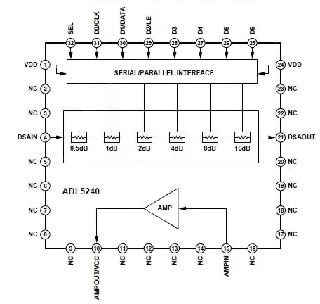
Figure 7: The ADL5240 from Analog Devices merges a 20 dB gain block with a DSA to yield a digitally controllable VGA which can provide both attenuation and gain.

Figure 8: The ADL5240 is an RF component reaching to 4 GHz, so it’s necessary that the vendor provides detailed s-parameter data, here in graphical format.
An interesting fixed-value attenuator is the E-TA series (e.g., E-TA2012) of 0 to 3 GHz thermal-variable units from Copal Electronics. These chip devices, approximately 2 × 3 mm depending on the specific unit, are available with eight temperature coefficients designated N1 to N8 and ranging from -0.0119 dB/dB/°C down to -0.0019 dB/dB/°C (Figure 9). These various coefficients are in addition to their available nominal attenuation ratings of 1 to 10 dB in 1 dB steps, depending on model selected.
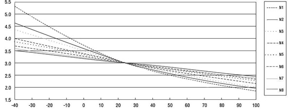
Figure 9: The E-TA series of 0 to 3 GHz thermal-variable attenuators from Copal Electronics are available with eight defined temperature coefficients; they can be used to compensate and stabilize the operation of RF-power amplifiers which occurs due to temperature drift by leveraging the change in attenuation of 2 dB to 5.5 dB as their temperature varies from -40⁰C to +100⁰C.
Summary
Although attenuation seems like an undesirable function and perhaps contrary to the goal of maintaining high SNR, it plays a critical role in many RF circuits for managing signal levels to prevent detrimental consequences due to overload and saturation. Even though they are apparently simple components, they have a full array of RF specifications including attenuation value and range (which can be fixed, continuously voltage variable, or digitally step-set variable), bandwidth, flatness, temperature drift, insertion loss, and more. Vendors provide a full range of impedance specifications beyond a nominal value, with s-parameters which users must take in account in their design modeling and analysis.
For more information about the parts discussed in this article, use the links provided to access product pages on the DigiKey website.
免责声明:各个作者和/或论坛参与者在本网站发表的观点、看法和意见不代表 DigiKey 的观点、看法和意见,也不代表 DigiKey 官方政策。


 中国
中国