ORing Controllers Facilitate Redundant Power Supply Design
投稿人:电子产品
2012-04-03
Datacenter servers, telecom systems, and military infrastructure equipment, among other mission-critical applications, cannot tolerate any failures or downtime. Hence, they use two or more power sources in a redundant power supply configuration to ensure that if one fails, the other supply can deliver full power without exception. ORing controller ICs are used to realize such redundant power supply configurations. Essentially, in this scheme, two voltage inputs are ORed to a common output. In the event one input supply fails or shorts, the ORing circuit protects the redundant bus and the system. Redundant power architectures are used on a variety of different bus voltages, ranging from <5 V to ± 48 V.
Because system power levels and density demands were less stringent in the past, ORing diodes were predominantly used for these applications. However, with power levels going up and the pressure to deliver high efficiency solutions rising, conventional methods are no longer acceptable for today’s high-end systems as diodes have a high forward voltage drop. That means with high current at high power levels, power dissipation is high as well. For instance, with a typical forward voltage drop of 400 mV for a Schottky diode, power dissipation is 800 mW, or a little less than 1 W, with 2 A of current drawn by the unit. Diodes that can handle this type of power dissipation are both large and expensive.
While a MOSFET offers an attractive alternative solution because its on-state resistance RDS(on) is very low (typically a few milliohms), and substantially lowers power loss as compared to a Schottky, it has a significant drawback. When a MOSFET is turned-on, current can flow in both directions through its channel. Consequently, if any input power source fails due to a short circuit, a large reverse current which can flow through the MOSFET and damage the redundant power source will be induced. Because of this, it is essential that the active ORing solution be very accurate and capable of extremely fast detection of reverse current fault conditions. To address this issue, the MOSFET is combined with a controller IC that can quickly detect the reverse current and shut the MOSFET off.
As such, the modern ORing solution is a combination of a controller IC and a MOSFET. However, due to high current consumption, only a few vendors have been successful in combining the controller and the MOSFET in a single package, while most suppliers are keeping the MOSFET external to the controller IC package. Once the fault is detected, the controller turns off the MOSFET as fast as possible to isolate the input fault from the redundant power source bus and prevent any further flow of reverse current. This, in turn, permits the redundant power source to take over.
Single package active ORing solutions
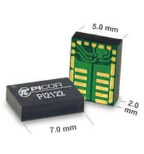
Power supply maker Vicor Corp. has developed a complete line of full-function active ORing devices called the Cool-ORing series. These combine a high-speed ORing controller and a very low on-state resistance N-channel MOSFET in a high-density, thermally enhanced land-grid-array (LGA) package¹ measuring just 5 x 7 mm. In this solution, typical on-state resistance can be as low as 1.5 mΩ, enabling up to 24 A of continuous load current over a wide range of operating temperature.
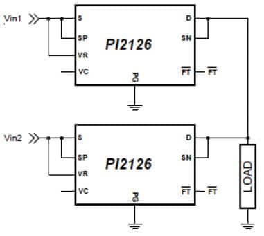
In comparison to conventional ORing solutions, Cool-ORing offers over 50% board space savings. In addition, the power loss is extremely low with dynamic response that can be as fast as 80 ns. For high-current applications, it can be paralleled in a master/slave configuration, (Figure 1). There are several members in this family with current-handling capabilities up to 24 A and input voltages up to 60 V. For instance, the PI2126 is a 30 V, 12 A Cool-ORing member designed for high-side ≤14 V bus applications. Likewise, the PI2127 is a 60 V, 12 A package suitable for high-side ≤55 V buses. The typical on-state resistances are 4.5 and 8.5 mΩ for the PI2126 and PI2127, respectively.

Figure 1: For high-current applications, PI2126 ORing controllers have been configured in a master/slave parallel configuration.
For use in low-side -48-V redundant power architecture, Cool-ORing offers the PI2003. Although, similar in functionality to the PI2126/27 series, it requires external industry-standard single or paralleled N-channel MOSFETs.
In some cases, systems employing redundant power architectures require protection not just against input power sources, but also from output load fault conditions. The Cool-ORing family also includes solutions that incorporate a load-disconnect feature, integrating a high-speed controller with back-to-back configured MOSFETs to provide an extremely low, effective on-state resistance solution (Figure 2). By having the back-to-back MOSFET arrangement, the internal parasitic body diodes are now opposing one another, so when the MOSFETs are turned off, the flow of current is prevented in both the forward and reverse direction. Tailored for low-voltage (≤5 V bus) high-side active ORing applications, parts such as the PI2122 offer a 7 V, 12 A solution with an effective 6 mΩ typical on-state resistance and fast dynamic response: 140 ns reverse current and 170 ns forward overcurrent turn-off delay time.

Figure 2: An ORing solution can integrate a high-speed controller and two back-to-back N-channel MOSFETs in a single package.
External MOSFETs
Due to high-current requirements, the majority of ORing controller IC suppliers are using the MOSFET switch externally. Some key suppliers in this category include Intersil, International Rectifier, Linear Technology, Maxim Integrated Products, and Texas Instruments.
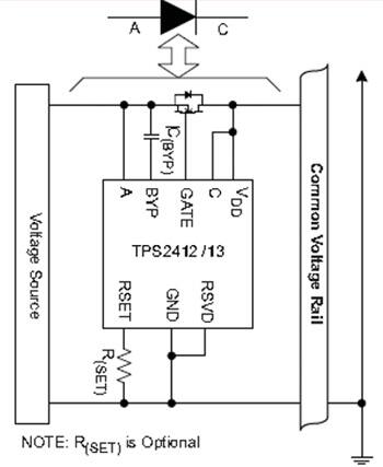
For instance, TI’s ORing controller TPS2412/2413 in conjunction with an external N-channel MOSFET can be used to combine multiple power supplies to a common bus in an N+1 configuration or combine redundant input power buses (Figure 3). It controls buses from 0.8 to 16.5 V and features an on/off gate control method. Internal tests show that a TPS2412/13 and N-channel MOSFET provide this function with less power loss than a Schottky diode.

Figure 3: In conjunction with an external N-channel MOSFET, TI’s ORing controller TPS2412/13 can be used to combine multiple power supplies to a common bus in an N+1 configuration, or combine redundant input power buses.
Many fault tolerant solutions also need hot-swap capability. For that, TI offers TPS2456, a dual 12 V protection/blocking controller. It uses external MOSFETs to provide both channel protection (hot-swap) and blocking (ORing) controller functions.
Unlike TI’s TPS2456, Maxim’s MAX5963 is a dual-channel hot-swap and ORing controller aimed at high-voltage power supplies with outputs from 7.5 to 76 V. The device controls external N-channel power MOSFETs to perform low-voltage-drop ORing, inrush current control, and current limiting functions. The current-limit function actively limits the current drawn by the load, protecting the load from a short-circuit condition.
Redundant power architectures are reliant on effective ORing solutions that address a wide range of bus voltages. These full-function solutions bring together high-speed controllers with high-performance MOSFET technology to enable extremely low loss solutions in a high-density thermally enhanced package. For more information use the links provided to product pages on the Digi-Key website.
Reference:
- Picor White Paper, "Active ORing Solutions in Redundant Power System Architectures"
免责声明:各个作者和/或论坛参与者在本网站发表的观点、看法和意见不代表 DigiKey 的观点、看法和意见,也不代表 DigiKey 官方政策。


 中国
中国