Optimizing Power Controllers in Industrial Motor Control with GMR10Dx Modules for Multiphase Bias Solutions

This article addresses the design challenges and key considerations involved in developing a reliable and safe multiphase power controller. It leverages the GMR10Dx isolated DC/DC converter module with floating outputs, paired with Ganmar Technologies’ highly integrated dual wide-bandgap switch gate drive power modules. The design and construction of these modules are optimized to meet system requirements in reliability, safety, EMI, and thermal management.

An illustrative system example is presented, showcasing a three-phase AC input powering a Power Factor Correction (PFC) stage, followed by a Pulse Width Modulation (PWM)-controlled heavy load such as an industrial-grade motor. The design is particularly focused on driving high-voltage GaN switches from Infineon (formerly GaN Systems), providing a practical circuit solution. Limitations in traditional methods for driving half-bridge (HB) totem-pole switches are addressed, and alternative solutions for controlling both upper and lower switches are explored. Practical circuit designs are presented to ensure reliable, safe operation while minimizing space requirements. Additionally, this note covers low-loss, high-bandwidth current sensing to further simplify the design process.

Today’s design environment presents numerous challenges, including the need for compact hardware, reduced power consumption for efficient cooling, increased reliability with optimized thermal management, and cost-effective solutions. These are further complicated by tight budgets and shorter development timelines. To address these challenges, this article introduces standard subsystems and building blocks that help design teams leverage the expertise and compliance of subsystem providers.

By utilizing Ganmar Technologies’ power converter and interface modules, this article offers an optimal solution to these design challenges. The provided modules enable efficient development of a multiphase gate drive system, while their standardized form factor conserves valuable real estate on the main board.

Designing a bias power controller for a general 3-phase high-voltage, high-power system using the GMR10Dx

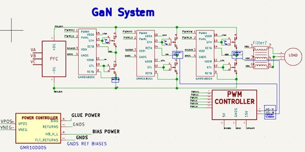
This section outlines the design considerations for creating a bias power controller in a high-voltage, high-power system using GMR10Dx DC/DC converter modules, along with the floating gate drive bias provided by the GMR04B00x modules. As shown in Figure 1a, the system may include a PWM-controlled heavy load, such as an industrial motor, incorporating multiple switches and requiring several bias voltages for different functional blocks. Below are key assumptions for the design:

  • EMI Considerations: The system requires a near-unity power factor, necessitating the use of a PFC.
  • Start-up Logic: The PFC includes a processor, which requires independent start-up logic for bias converters.
  • Power Dissipation: Reducing power dissipation in the controller electronics is critical for reliability and for simplifying cooling system requirements.
  • Use of Off-the-Shelf Products: The design maximizes the use of readily available components.

Figure 1a provides an overall system configuration for visual reference in subsequent design discussions.

Image of industrial high load control system bias and startupFigure 1a: Industrial high load control system bias and startup. (Image source: Ganmar Technologies)

Referring to the block diagram in Figure 1a, this section will focus on designing the Bias Power Controller and its integration with the overall system. Design options will be explored for each function, excluding the PFC and PWM Controller, due to the need for more specific information on system interface requirements to thoroughly address these functions. Consequently, this article will not cover those components in detail. It is assumed that the system employs high-voltage GaN switches, such as the GS66516T from Infineon, although considerations for alternative switch technologies, like SiC or bipolar switches, will also be discussed.

Additionally, this article will showcase the highly integrated, self-powered floating gate driver modules from Ganmar Technologies, specifically the GMR04B00x. The “x” in the model number indicates various dual gate driver chip options available. Refer to the GMR04B00x datasheet for detailed specifications and options.

Bias power controller

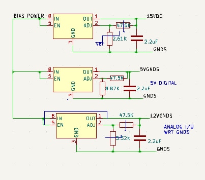
The Bias Power Controller is designed to offer brownout protection for low AC input values (UVLO) and provide an unlatched shutdown if AC inputs exceed the maximum set limit (OVLO). When the AC input is within safe operational values, the GRM10Dx module generates isolated DC outputs at common voltages, typically 6 V and 22 V. In larger systems, additional voltage forms may be required. Figure 1b illustrates a typical configuration for obtaining these voltages. A low power 5 V output is used to power the dual gate driver chip in the GMR04B00x module, specifically the Analog Devices ADUM7223. Refer to the GMR04B00x datasheet for other available options.

Diagram of typical glue circuit forms derived from the Ganmar Technologies GMR10DxFigure 1b: Typical glue circuit forms derived from the GMR10Dx. (Image source: Ganmar Technologies)

The GMR04B00x module internally powers its floating side to provide two 12 V biases. The high-side 12 V (12VH) biases the VIA output driver for the upper power switch, with the gate drive level at +5.6 V/-5.6 V relative to the HBU node. Similar split drive configurations are applied around the V and W phase circuits.

For the lower-side switch, a separate 12VL is generated internally by the GMR04B00x module, which can be referenced with the low-side power return node of any polarity. The VIB output of the ADUM7223, for instance, is split into +5.6 V/-5.6 V by the splitter network, ensuring that the lower GaN switch operates correctly.

For SiC switches, a different version of the GMR04B00x module provides 15 V, 18 V, or 22 V, which can be factory-set to suit various high-power SiC switches. The splitting circuit outputs provide ±floating bias for driving silicon carbide switches on both high and low sides relative to the HBU/V/W upper nodes and similarly for lower nodes of any polarity. Refer to the GMR04B00x datasheet for available options.

The Bias Power Controller section, along with the illustrated LDOs in Figure 1b, powers the other two GRM04B00x interface modules connected directly to the gates at the V and W nodes. Additionally, the 22 V output can power analog controllers, digital sections, and I/O chips on the user's board via LDOs. For higher power needs, users can consult Application Note for guidance on paralleling GMR10Dx modules.

Start-up issues

It is crucial to provide a stable power source for digital processors before they become operational. This requires operating the bias controller from a power source independent of the PFC. The Ganmar power converter circuitry consumes up to 18 watts from the AC source, which minimally impacts the phase relationships of the AC input. The GMR10DX module supports an input voltage range of 100 VDC to 320 VDC, covering the typical range for off-line applications.

For higher source voltages often encountered in high-power applications, where rectifiers may produce up to 380 V, please consult Ganmar Technical Support for other options within the GMR10Dx series.

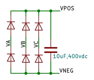
Figure 2 depicts a typical 6-diode bridge rectifier suitable for system start-up with this module. Once the AC input exceeds approximately 42 VRMS (60 Hz or 400 Hz), resulting in a 200 VDC output from the bridge with a small 10 µF capacitor, the modules will begin producing outputs with a maximum delay of 70 ms under low load conditions. This delay is acceptable as no other system blocks are drawing power during start-up.

During transient events, if the AC inputs cause the 6-diode bridge rectifier output to exceed the safe operating range of the converter module, the module will shut down until the rectified voltage returns to a safe level. Additionally, an under-voltage brownout protection feature activates if the rectified voltage drops below 100 V.

Diagram of drawing a maximum of 18 W from the AC input directly for startup and biasinFigure 2: Drawing a maximum of 18 W from the AC input directly for startup and biasing. (Image source: Ganmar Technologies)

Input filtering

Power switching modules, such as the GRM10Dx, exhibit a "negative" impedance characteristic towards their input power sources. This characteristic necessitates careful filter design to ensure stability at the interface. While detailed design of input filters is covered extensively in various reports and publications, this aritcle provides a brief overview of the GRM10Dx module's input characteristics.

For a typical 15 W constant power load due to GaN driving, with a rectifier voltage of 200 V and an efficiency of 0.85, the equivalent impedance is calculated as |200²/(15/η)|, resulting in approximately 3.14 kΩ. This impedance is relatively high compared to the source impedance, making it easier for the required filter to bypass it effectively. However, it is advisable to install a 10 µF/400 V damping capacitor close to the GRM10Dx module. The module itself includes a 0.47 µF capacitor to handle instantaneous current peaks from internal switching events. The Equivalent Series Resistance (ESR) rating of the external capacitor is not critical, provided the main PFC filter offers sufficient damping.

Ganmar Technologies also provides a legacy AC input bridge rectifier module, complete with a fuse and EMI filter, for easy integration with the GRM10Dx module. This simplifies the process of connecting to the AC source. For details on integrating this module, please consult Ganmar Technical Support.

Driver biasing

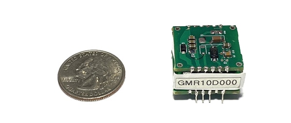
Figures 3 and 4 show the schematic and a photo of the GMR10D000 module, an isolated DC/DC converter capable of delivering 15 W with dual outputs. VOUT1 typically provides 6.5 V at 3 W, while VOUT2 provides 22 V at 12 W. Both outputs reach their steady state within 10 ms. This section will explain how to connect the functions illustrated in Figure 1 to the GMR10Dx devices to achieve the desired functionality and performance.

Diagram of connection 3-phaseFigure 3: Connection 3-phase. (Image source: Ganmar Technologies)

Image of Ganmar Technologies GMR10D000 moduleFigure 4: The GMR10D000 module. (Image source: Ganmar Technologies)

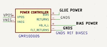
Figure 5 illustrates the module interconnections of multiple GMR10Dx modules to fulfill the functions of the Bias Power Controller. In this section, a detailed explanation of the application of GMR04B008 in the context of the HS-U block is provided. The other two modules can be replicated easily by connecting reference returns that correspond to their respective nodes.

Diagram of Module driving side functional schematicFigure 5: Module driving side functional schematic (shown with GMR10D005). (Image source: Ganmar Technologies)

Figure 6 showcases the availability of 22 V power with respect to the commonly referenced "ground" GNDS node.

Image of Ganmar Technologies GMR04B00x internal schematicFigure 6: GMR04B00x internal schematic with floating gate power and direct drives. (Image source: Ganmar Technologies)

Power stage interface requirements

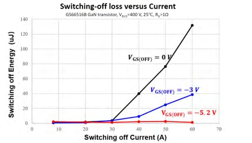
As shown in Figure 6, it is generally recommended in GaN systems to apply a negative bias voltage to turn off GaN power devices, particularly in hard switching topologies where currents exceed 30 A. Figure 7 provides illustrative plots (courtesy of the Infineon Webinar) demonstrating this approach.

Graph of effects of VEE on turn-off dynamicsFigure 7: Effects of VEE on turn-off dynamics. (Image source: Infineon)

Implementation and Turn-On/Turn-Off Characteristics - The module’s implementation of splitters for Infineon devices ensures efficient Turn-On and Turn-Off voltages while minimizing off-transition losses. The split drive waveforms and Infineon’s GS66xx design contribute to enhanced efficiency, alongside a unique transformer design that reduces ringing peaks during the GS66xx’s turn-off process.

Turn-on/turn-off

For a complete Turn-On, a 5.6 V gate drive is required, with minimal parasitic inductance and capacitive coupling between sensitive switching nodes and traces. Adherence to the GaN vendor’s guidelines for proper placement and routing of circuitry is essential.

During Turn-Off, the gate-source voltage (VGS) should be significantly lower than the threshold voltage (VTH), with a reference level of approximately 0 V in the circuits discussed here. This article assumes the use of the ADUM7223 Gate Driver IC from Analog Devices. It is important to note that the driver’s output Under Voltage Lockout (UVLO) is 5 V, making it suitable for the 5.6 V gate drive required by GaN devices. Power dissipation by the driver for this GaN can be calculated using the driver’s datasheet:

PD = (VDDI)(IDDI) + 2(IDDx) + (f)(Qg)(VDDx)[Rp/Rp+Rg] + (f)(VDDx)[Rn/Rn+Rg] + 2fCINT VDDx2

Assuming 250 kHz switching and the values below, A PD can be calculated:

VDDI IDDI IDDX VDDX F QG RP RG RN CINT PD DRiver
5 0.01 0.004 6 250000 8.25E-09 2.7 10 1 3.7E-10 1.084159E-01

The driver configuration results in a dissipation of 100 mW, which is well within the capabilities of the GMR10Dx and GMR04B00x modules. The GMR10Dx module is capable of providing significantly more power than required for the driver, ensuring a robust power supply for its operation.

HV GaN setup for driver

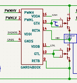
The GMR10Dx module supplies the necessary bias voltages for both the upper and lower GaN drivers in a Half-Bridge (HB) configuration. Figure 8 illustrates the connections for the GaN drivers from the splitters.

Proper referencing of the bias returns is crucial to prevent erratic switching behavior and potential damage to the GaN devices. Users should adhere to the guidelines and recommendations provided in the specific GaN datasheets and application notes to ensure correct and safe operation. Additional guidance can be found in the application briefs of the GMR04Bx Dual Direct Driver Integrated module datasheet.

Image of totem pole arrangement and classic half-bridge configurationFigure 8: Totem pole arrangement and classic half-bridge configuration with split drive direct connections to GaN switches. (Image source: Ganmar Technologies)

The GMR04B00x module supplies the necessary floating bias voltage for the upper GaN switch gate driver, eliminating the need for additional circuitry such as a flying bootstrap capacitor to generate the required bias voltage.

With the GMR04B00x modules, the floating gate drive voltages can be directly connected to the gates of both the upper and lower GaN switches, providing a stable ±5.6 V gate drive. This approach simplifies the design by removing the need for the controller to switch the lower device to generate the bias for the upper gate driver.

Using the GMR04B00x modules allows the desired gate drive voltages to be achieved for both the upper and lower GaN switches without the complexity and additional components required by alternative biasing methods.

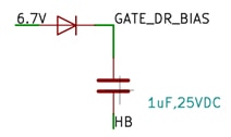
The legacy bootstrap scheme as shown in Figure 9 has several drawbacks, including the need for additional components like diodes and non-polar capacitors, whose values might need adjustment based on the specific requirements of GaN or other devices. Startup issues and the lack of a stiff bias are significant concerns with this approach. Additionally, the legacy bootstrap scheme is incompatible with bipolar HB nodes.

Image of legacy floating gate driver bias schemeFigure 9: Legacy floating gate driver bias scheme. (Image source: Ganmar Technologies)

In contrast, the compact layout of the GMR10Dx and GMR04B00x modules, along with their associated extensions, highlights their space-saving advantages. This makes them a practical solution for applications requiring efficient biasing and proper referencing.

Current sensing

Figures 10 and 11 illustrate the integration of current sensing using shunt resistors with the GMR10Dx and GMR04B00x modules. Shunt resistors are commonly used to measure and monitor the current flowing through a circuit. By placing these resistors strategically in the current path, the voltage drop across them can be measured and used to calculate the current.

In the context of the GMR modules, current sense shunt resistors are connected in series with the load or a high-bandwidth isolated current sense module. This setup ensures accurate current sensing and monitoring. The GMR modules provide the necessary floating or ground-referenced bias voltages and power to support the current sensing systems, ensuring reliable and precise measurements.

Incorporating current sensing into the system design allows users to gather valuable information about current levels and monitor circuit or system performance. This is particularly useful in applications requiring precise current control or protection, such as motor control, power electronics, or renewable energy systems.

Image of legacy shunt resistor current sensingFigure 10: Legacy shunt resistor current sensing. (Image source: Ganmar Technologies)

Image of Ganmar Technologies GMRCS000 non-dissipative current sensingFigure 11: GMRCS000 non-dissipative current sensing. (Image source: Ganmar Technologies)

Ganmar Technologies offers the GMRCSN000 and GMRCSP000 modules as compact, isolated, non-dissipative current sensor solutions. These modules provide high-bandwidth isolated current sensing without requiring additional shunt resistors in the current path. This eliminates power losses and simplifies the design.

The GMRCSN000 and GMRCSP000 modules detect the current flowing through the circuit and offer two output polarities: 0 to +Vsense and -Vsense to 0. These output ranges are suitable for direct interfacing with the ADC (Analog-to-Digital Converter) of embedded controllers or for analog controllers used in bridgeless PFC applications.

Utilizing the GMRCSN000 or GMRCSP000 modules simplifies current sensing implementation, conserves valuable board space, and ensures accurate and isolated current measurements. For more information about these modules and their applicable part numbers, contact Ganmar Technologies' technical support for detailed assistance and integration guidance.

Conclusion

This article has detailed a comprehensive design approach for system startup and biasing using the GMR10Dx and GMR04B00x modules in conjunction with high-voltage, high-power GaN switches. The focus is on GaN switches from Infineon, which are commonly used in applications such as 3-phase motors, 3-phase inverters, and Level 3 EV chargers.

The design offers several advantages over legacy approaches, including enhanced reliability, compactness, and efficiency. The GMR10Dx and GMR04B00x modules provide a versatile and robust solution for system startup and biasing, offering direct connections to the gates of these switches.

Additionally, the article introduced the GMRCSN000 and GMRCSP000 modules, which offer a compact, non-dissipative current sensing solution with flexible output capabilities. These modules simplify current sensing implementation and provide accurate, isolated current measurements.

For customers interested in implementing these designs with Ganmar Technologies’ components, schematics, BOMs, and layouts (where applicable) are available in KiCad-compatible Altium format. For further discussions, pricing inquiries, and availability, please contact Ganmar Technologies' technical support or sales team.

By leveraging the design approaches and solutions presented in this article, designers can significantly enhance the performance and reliability of their systems utilizing GaN switches. Additionally, they can benefit from the expertise and support provided by Ganmar Technologies.

免责声明:各个作者和/或论坛参与者在本网站发表的观点、看法和意见不代表 DigiKey 的观点、看法和意见,也不代表 DigiKey 官方政策。