MCU Solutions for Automotive CAN Networking
投稿人:电子产品
2013-10-23
The automotive industry has embraced diagnostic buses. These fairly straightforward, low-cost, serial interfaces allow automakers to connect sensors, actuators, power controls, buttons, switches, displays, indicators, and so on. The complex, expensive, and often unreliable wiring bundle harnesses of the past are all but gone.
This is also a boon to both professional mechanics and 'do it yourselfers'. Low-cost readers can help troubleshoot issues with modern cars and engines. As it taps into the car’s electronics, we have access to engine statistics, real time sensor data, settings, modes, stored alerts, and error codes.
Many embedded designs take advantage of this connectivity, from low-cost signal pass-through and intercepts (for remote starters), through handheld data terminal types of readers, to more complex real-time data acquisition tools for racing and other high-performance applications.
As a result, there is a range of microcontrollers, from small 8-bit to high-end 32-bit parts, that target this large and receptive crowd via the CAN bus, a vehicle bus standard designed to allow microcontrollers and devices to communicate with each other within a vehicle without a host computer. This message-based protocol was designed specifically for automotive applications, but is now also used in areas such as aerospace, industrial automation, and medical equipment.
This article looks at microcontrollers supporting CAN applications. All parts, datasheets, tutorials, and development systems referenced in this article can be found on the DigiKey website.
A common standard
The state of California began legislating the use of control systems to combat smog back in 1966. These ideas made their way into the clean air act of 1970, and the use of computerized automotive systems to reduce emissions was born.
By 1988, the Society of Automotive Engineers (SAE) had defined standard diagnostics, connectors, and signals. After the EPA adopted most of the SAE criteria, OBDII became the extended set of standards in 1996. Since 1996, the basic OBDII protocols have been split as follows, European and Chrysler used ISO 9141 (or KWP2000), Ford used the pulse-width modulated SAE J1850, and GM used SAE J1850 with variable pulse-width modulation.
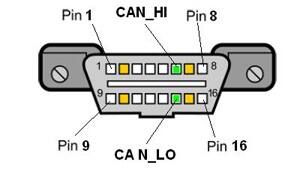
In 2008, it became mandatory that all cars sold in the U.S. use the modern OBDII protocols employing CAN twisted-pair signaling, or ISO15765-4, which uses the standard SAEJ1962 connector and differential signaling on pin 6 and 14 for communications (Fig. 1). The only variations are identifier length and bus speeds (Table 1).
| Variant | Identifier Length | Bit Rate |
| 1 | 11 bit | 500 Kbaud |
| 2 | 29 bit | 500 Kbaud |
| 3 | 11 bit | 250 Kbaud |
| 4 | 29 bit | 250 Kbaud |
Table 1: The modern ISO15765-4 connections vary with identifier bit length and data rates.
The de facto standard ELM327 command set is similar to the AT-style command set used by Hayes modems. ASCII strings and parameters kick-off function and return status information on engine data, codes, and more. Because of the free-flowing availability of information, ROM-based look-up tables can hold code meanings accessible to firmware. Older cryptic codes are easily decoded using Internet search engines. In addition, how-to fix-it posts and videos make it easier than ever for individuals to take advantage of the OBDII and CAN interface.
Just hanging on the bus
Several types of products are in good position to take advantage of OBDII to tap into the car’s electronic systems. Since CAN allows multi-masters on the bus using a collision detect and avoidance scheme, it is relatively easy to add computing horsepower to a CAN bus-controlled vehicle. All nodes use mailboxes and buffers to share and obtain data from each other, listen for the commands, and jump in when addressed.
In addition to static measurements, real-time engine data is available over OBDII. This allows custom gauges and instrument clusters on a multi-functional display, especially important for modern vehicles that do not even have a temperature gauge on the dashboard. In addition, performance-enhancing chips for the car’s computers allow power users to fine-tune performance or economy settings (usually at the risk of violating terms of the car’s warranty).
It is important to know that the framed packets on the CAN bus are UART-style data strings. As a result, any microcontroller that has a UART with a good timing-control circuit that can maintain accuracy at non-standard baud rates is a viable candidate for CAN control.
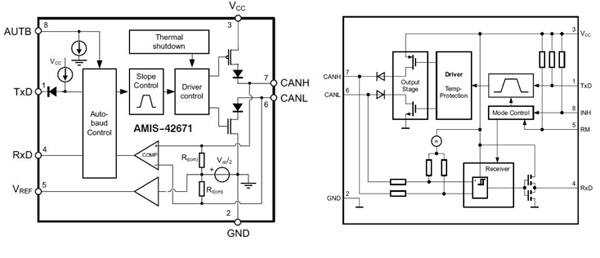
On the other hand, the physical interface uses a half-duplex differential signaling technique that most UART-based micros do not support. As a result, to patch a UART into CAN will require a CAN transceiver chip like the Infineon IFX1050G (Fig. 2A), or the ON Semiconductor AMIS426711CAB1RG (Fig. 2B). These types of physical layer interface chips adapt the logic level TX and RCV lines to the electrically isolated or non-isolated automotive bus.
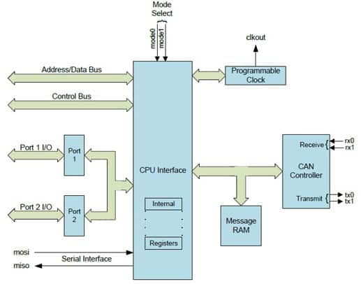
Microcontrollers with built-in differential transceivers can be general-purpose or application specific. Take for instance the Innovasic IA82527PLC44AR2 CAN Controller IC (Fig. 3). It is form, fit, and function compatible with the legacy Intel 82527 Communications controller with a facelift for CAN support. Peripheral-style CAN support also comes from Microchip with its MCP2515T-1/ML SPI-accessible standalone CAN controller, and from NXP with its SJA1000T/N1,118 standalone CAN controller with parallel interface.
Legacy architectures do a fine job of handling the CAN data. The 8-bit, 50 MHz Silicon Labs C8051F550-IM has a CAN controller built-in as a peripheral to the well-liked 8051 core processor (Fig. 4). The 1.8 to 5.25 volt parts use mostly single-cycle instructions giving it up to a 12x performance compared to the older 8051s.
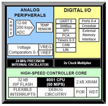
Other on-chip peripherals include I²C, SPI, UART, and 12-bit A/D. The company also provides the C8051F560DK development kit that takes advantage of the on-chip serial debug interface and emulator port. A Serial Communications Overview Product Training Module is also available on DigiKey’s website.
For a bit more horsepower, 16-bit parts like the Freescale MC912D60ACFUE8 could be a good choice. As part of the company’s HC12/HC16 family, these 16-bit parts are upwardly code compatible with the familiar 68HC11 family of processors with 20-bit ALU, mixed-signal support, and differential CAN bus pins.
A key benefit to the Freescale part is the msCAN software that provides message scheduling and prioritization, as well as advanced buffer management for coordinating multiple messages and activities. Of particular interest are two maskable, identifier acceptance filters for compliance with the CAN 2.0 B extended identifier modes. The Freescale parts also have serial debug/emulation ports and internal EEPROM, as well as Flash.
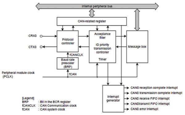
More complex designs may include driving high resolution LCD’s and TFTs, while also integrating Ethernet, GPS, Wi-Fi, Bluetooth, or USB. These designs will need more I/O, wider data paths, external buses and, in general, more horsepower. Many off the shelf-embedded processors are ready to serve here such as the Renesas RX600 series of 32-bit MCUs with CAN support. The 32-bit RX CPU core delivers 165 DMIPS at a maximum operating frequency of 100 MHz, and the Renesas MCUs implement one channel (32 mailboxes) of the CAN module (Fig. 5) that complies with the ISO11898-1 specifications. The CAN module transmits and receives both formats of messages, namely the standard identifier (11 bits) and extended ID (29 bits). Renesas also offers a Product Training Module entitled CAN peripheral and API.
Summary
The automotive processing environment is much easier to diagnose and control using OBDII and CAN. A number of device makers provide parts and kits to help get you started. With standardized connectors, messaging protocols, and signaling levels, there is nothing stopping engineers from fully utilizing the car’s computers to add features, functionality, or to improve performance or economy.
For further information on the parts discussed in this article, use the links provided to access product pages on the DigiKey website.
免责声明:各个作者和/或论坛参与者在本网站发表的观点、看法和意见不代表 DigiKey 的观点、看法和意见,也不代表 DigiKey 官方政策。


