LED Dimming Solutions
投稿人:电子产品
2012-06-26
The market for LED lamps has grown exponentially as residential and commercial customers make the change, from incandescent and even CFL, to LED lighting. The typical reasons are better power efficiency and much longer lifetime. However, customers also want the same features in LED lamps that are provided for the incandescent; specifically, the ability to dim the light because it provides the right ambience and it helps save energy. At first glance, it seems simple to design in a dimmer, but in fact it is really challenging because LEDs and incandescent lamps operate differently, and if not done correctly, the dimmer will cause flickering in the LED lamp, as well as a reduced dimming range and inconsistent performance. During dimming, LED lamps can demonstrate a pronounced and obvious flicker when attached to traditional leading- edge dimming circuits. An LED driver connected directly to a line-voltage incandescent dimmer also may not receive enough power to operate at lower dimming levels or it may be damaged by current spikes. Another flicker source is the mains power instability. If there is a drop in the supply, the lamp will simply switch off, producing a noticeable flicker as the lamp's driver circuitry tries to keep the light output constant.
Incandescent lamps
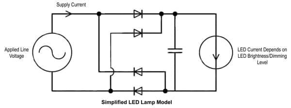
Currently, residential and commercial lighting control equipment is designed for incandescent lamps. The incandescent lamp is a simple resistive load with a linear response to the dimmer set point. LED lamp loads can vary greatly across different manufacturers’ lamps and designs, but most can be characterized by a diode-capacitor power supply feeding a constant current source. The diodes rectify the applied AC voltage, allowing it to charge the storage capacitor, while the LED elements draw a constant current from the power supply that is related to the desired dimming level and brightness.
LED lamps
LED lamps have a nonlinear relationship, and the applied voltage and current flowing into the load are related. The incandescent lamp load, applied voltage across the load, and the resulting current flowing through the load, are related linearly.
In LED loads, the applied voltage and resulting current flow are not related by a simple linear relationship. In the diode-capacitor power-supply model of the LED lamp, current flows from the applied voltage to the load only when the magnitude of the applied voltage exceeds the stored voltage on the power supply capacitor (Figure 1). The stored voltage on the power supply capacitor, in turn, depends on the current drawn by the LED elements themselves, which is a function of the LED brightness.

The current flowing from the supply to the lamp depends both on the instantaneous value of the input AC-voltage waveform and the brightness of the LED lamp. Changing the intensity or dimming level of the LED lamp affects where in the AC-line cycle the load begins to draw current. This also affects the amount of current that surges into the lamp at this point of the line cycle. The relationship between these current peaks, and the times in each line cycle where these current peaks occur, depends nonlinearly on the lamp design, the LED brightness, and the set-dimming level.
One solution is the use of advanced line synchronizing techniques that resist the effects of irregular load currents. In older lamp-dimming devices, line synchronization is accomplished using simple zero-crossing detection. This method used a circuit to detect when the AC-line voltage switches polarity and crosses the zero-voltage point. The zero-crossing method still is used in older designs because it requires simple circuitry; it is practical and it works for incandescent lamps.
However, for LED loads in two-wire applications, the simple zero-crossing technique is sometimes not enough. Fortunately, advances in microcontroller technology have made putting advanced synchronization algorithms and approaches within the grasp of cost-sensitive designs with tight power constraints. Using a low-power microcontroller in the dimmer allows advanced software to handle the difficulties of measuring the AC-line cycle with the irregular line currents present in two-wire LED load applications.
Additional compatibility issues between lamps and dimming devices often stem from a lack of dimming performance standards within the lamp industry and how they correspond with LED drivers, leading to a wide-range of inconsistencies among products. This lack of standardization can be seen not only in varying characteristics between manufacturers, but also by products within product lines. Complications also arise because a lamp can require a set of electrical and electronic characteristics, such as current, voltage, amperage, and control signals that are very different from another lamp.
The National Electrical Manufacturers Association (NEMA) and other single-source lighting committees have developed the SSL 6-2010 standard2, which provides guidance to LED lamp manufacturers for suitable operation on standard incandescent phase cut dimmers. However, the current NEMA standard does not provide a rating scale or detail what is considered compatible. While serving as a starting point, these standards are still incomplete and require additional amendments to ensure complete consistency among dimming devices and lamps.
Under UL 14723, which is intended to regulate the safety of dimmers, LED and CFL lamps are categorized as electronic ballasts. The standard addresses in-rush current that is generated at the start-up of many LED and CFL lamp loads. This high in-rush current can result in switch contact failure, which is a safety hazard in many field applications such as dimmers, where the switch serves as the disconnect device. The UL standard takes the systems approach to evaluate the safety of the combination of the dimmer and electronic ballasts, CFL, or LED lamp, by requiring dimmer manufacturers to provide information on the intended electronic load for each dimmer.
Driver circuit methods
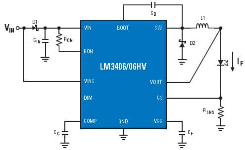
Two popular methods for dimming LEDs in switched-mode driver circuits are Pulse-Width Modulation (PWM) dimming and analog dimming. Both methods control the time-averaged current through the LED, but there are di?erences between the two. Simply put, analog dimming of LEDs is the adjustment of the constant LED current level. Analog dimming can be accomplished by an adjustment of the current sense resistor RSNS or by driving an analog voltage on a DIM function pin of the IC. A change in value of RSNS will correspond to a change in LED current with a ?xed CS reference voltage.
An important disadvantage to analog dimming is that the color temperature of the emitted light can vary as a function of LED current. So for applications that require a constant color temperature, analog dimming is not suitable.
The PWM method of dimming requires turning the LED current on and off for short periods of time. While PWM reduces color changes in the LED with varying brightness levels found in the analog method, it is at the expense of additional circuitry. The frequency of this start-restart cycle must be faster than the human eye can detect to avoid a ?ickering e?ect. About 200 Hz or faster is usually acceptable.
With PWM, dimming of the LED becomes proportional to the duty cycle of the dimming waveform, according to the formula:4
IDIM-LED = DDIM x ILED
Where IDIM-LED is the average LED current, DDIM is the duty cycle of the dim waveform, and ILED is the nominal LED current setup with the selection of RSNS.
PWM LED drivers often feature a specialized PWM dimming pin that accepts a wide range of PWM frequencies and amplitudes, allowing a simple interface to external control logic.
Two-wire PWM dimming is a popular method for automotive interior lighting. As VIN is modulate below 70 percent of VIN-NOMINAL, the VINSM pin (Figure 2 showing the National LM3406) detects the change in voltage and converts the PWM waveform into a corresponding PWM of the output drive. The disadvantage to this method is the power source to the converter must contain a circuit to provide a PWM waveform to its DC output.

Dimming control parts
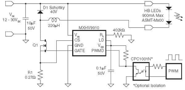
Other examples of LED dimming control include the MXHV9910BTR, a high-brightness (HB) LED driver manufactured using IXYS high-voltage BCDMOS on SOI process. This driver has internal circuitry that allows it to operate from a universal AC line or from 8 to 450 VDC. LED dimming can be implemented by applying a small DC voltage to the LD pin or a low-frequency digital PWM signal in the range of a few hundred hertz to the PWMD pin. The PWMD signal controls the LED brightness by gating the PWM gate driver output pin gate. The signal can be generated by a microcontroller or a pulse generator with a duty cycle proportional to the amount of desired light output. When PWMD is low, gate drive is off; when PWMD is high, gate drive is enabled.
A linear dimming function can also be implemented on MXHV9910BTR (Figure 3) by applying a DC control voltage to the LD pin. By varying this voltage, the user can adjust the current level in the LEDs, which in turn will increase or decrease the light intensity. The control voltage to the LD pin can be generated from an external voltage divider network from VDD. This function is useful if the user requires a LED current at a particular level and there is no exact Rsense value available. A combination of linear and PWM dimming techniques can be used to achieve a large dimming ratio.

Design engineers also will find a plentiful selection of design kits/evaluation boards. For example, Power Integrations’ LED dimmer Ref Design Kit includes a single-stage PFC, primary-side constant current control, and triac dimming/non-dimming options. Another is the Texas Instruments LED dimmer evaluation board for the LM3445 Triac Dimmable Offline LED Driver. This is a triac dimmable offline LED driver and demonstration board capable of automatically adjusting the LED current and light output in relation to the triac firing angle.
Summary
This article has discussed the challenges and solutions of LED dimming. It has reviewed the two main categories of LED dimming: PWM and analog, noting that both have advantages and disadvantages: Analog dimming is usually a simpler circuit, but may be inappropriate for applications that require a constant color temperature; PWM dimming does not have the same issues with color changes in the LED for varying brightness levels, but requires additional logic to create the PWM waveforms. For more information on the products mentioned here, use the links provided to access product information pages on the DigiKey website.
References:
- Addressing Today’s Dimming Challenges with a Universal Control, Marc Gallo, Michael Neary; Leviton White paper, March 2012
- NEMA SSL 6-2010 standard
- UL Standard 1472
- Dimming Techniques for Switched-Mode LED Drivers — By Rich Rosen, Field Applications Engineer, National Semiconductor Power Designer
免责声明:各个作者和/或论坛参与者在本网站发表的观点、看法和意见不代表 DigiKey 的观点、看法和意见,也不代表 DigiKey 官方政策。


