Implementing Industrial Ethernet with 32-bit MCUs
投稿人:电子产品
2014-07-09
Ethernet’s dominance in enterprise networking gives it an obvious advantage in the industrial networking space. Using a single-core protocol across the enterprise allows data to flow seamlessly from the factory floor to the business units, making it possible to manage production schedules more efficiently, minimize inventory costs, and optimize maintenance operations.
Ethernet was not designed for the factory floor, however, and the chief shortcoming of standard Ethernet is that it cannot provide the real-time response required by many industrial applications such as process and motor control. For a couple of decades, deterministic protocols such as CAN (Controller Area Network) and PROFIBUS (Process Field Bus) dominated industrial networks. Although these protocols still maintain sizeable market shares, a few years ago Ethernet variants started to appear that provided the real-time performance that standard Ethernet lacked.
In order to rationalize the unproductive diversity that developed in industrial networking, in 2001 the Open Device Vendor Association (OVDA) was formed to create and maintain the Common Industrial Protocol (CIP) to ensure some level of compatibility. Since then, several protocols, including EtherNet/IP, DeviceNet, ControlNet, and CompoNet have implemented CIP in the upper levels of their protocol stacks. Hundreds of vendors now support CIP.
EtherNet/IP is the name given to CIP when it is implemented over standard Ethernet as defined by IEEE 802.3. The “IP” in EtherNet/IP stands for Industrial Protocol.
EtherNet/IP Technology
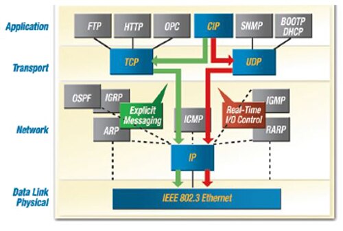
Figure 1 shows how a multistandard environment can be realized using CIP. The red arrows from the CIP block in the top tier define the path to real-time control via UDP. Green arrows show the path for standard IEEE 802.3 Ethernet. Taken together, they comprise EtherNet/IP. Products can be developed using existing TCP/IP stacks, or, in industrial applications, an existing Modbus interface can simply be modified to communicate with PLCs.

CIP uses an object model to simplify software development. A set of objects and device profiles relating to common interfaces and behaviors are defined in the application layer. CIP uses three classes of objects: Application objects, which define a method to represent device data; Network objects that define Ethernet/IP-specific functions and how parameters such as IP addresses are configured; and Communication objects that create a way to establish communication associations and access device data and services.
End-to-end communication between devices on CIP networks is handled by CIP communication services. Multivendor interoperability is ensured because EtherNet/IP maps CIP communication services to Ethernet and TCP/IP.
Components of an EtherNet/IP node
Every EtherNet/IP node consists for four layers that correspond to the OSI model. They are as follows:
- The physical layer (PHY). Any standard Ethernet media (twisted-pair copper or fiber-optic) can be used as long as it supports 100 Mbit/s data rates.
- The data link layer transmits packets from device to device and contains the Ethernet/IP MAC, which can be implemented with an ASIC, FPGA, or, custom hardware running high-speed firmware.
- The session/transport layer, which handles TCP/IP as well as UDP/IP for real-time messaging. CIP object definitions are also in this layer to enable communication with the application layer.
- The application layer. Inside the node, the application can run on hardware or a hardware/software combination implemented by an embedded CPU. The application must, of course, support EtherNet/IP-based protocols.
Designers have multiple architecture choices when implementing an EtherNet/IP node. As long as the node is implemented entirely in hardware, ASICs, FPGAs or board-level solutions can be used. Although these straightforward digital I/O device solutions are suitable for cost-sensitive products, and application that requires configuration, monitoring and control typically require an MCU as well. Sensors, for example, are typically controlled by an MCU. In an EtherNet/IP node, the MCU can also implement the device driver and run the EtherNet/IP protocol stack. The ASIC or FPGA is still an integral part of the architecture.
Embedded MCU Implementation
A more sophisticated architecture implements the EtherNet/IP node as a peripheral in an MCU with an integrated CPU. This architecture is shown in Figure 2. The processor may be configured using available gates in an FPGA.

Figure 2: Integrated EtherNet/IP node with processor (Courtesy of Texas Instruments).
Instead of using an MCU with the EtherNet/IP node as a peripheral, the topology can be reversed and the MCU can be implemented on the same FPGA or ASIC that implements the EtherNet/IP node. From a design perspective, this approach requires careful consideration of the processing power and clock frequency required of the embedded MCU, both for the target application and possible future design spins. FPGA implementations may also make it a challenge to meet product price targets.
Regardless of how it is implemented, the MCU requires some means of executing real-time operations with another embedded peripheral for just this purpose.
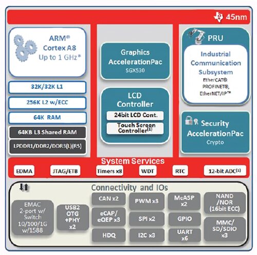
’ Sitara™ AM33x processors, for example, handle this issue with the Programmable Real-time Unit (PRU) that supports very low-level interaction with the two PHY transceiver chips that are part of the solution shown in Figure 2. Using firmware, the Sitara AM33X processors encapsulate the entire Ethernet MAC layer in the PRU subsystem.
To optimize transmission efficiency, EtherNet/IP nodes process only those packets specifically addressed to them. Interrupts are used to maintain real-time communication between the application and the ARM processor. Since almost all of the low-level, high-speed EtherNet/IP functionality is handled by the PRU subsystem, the ARM processor can allocate virtually all of is processing power to running the stack and complex applications such as motor control.
TI’s Sitara AM335x processors are powered by an ARM Cortex-A8 processor and operate from 275 MHz for basic applications up to 1 GHz for high-performance applications such as motor control.
The Sitara AM3352 is available in 275 MHz (AM3352ZCE27), 600 MHz (AM3352BZCZ60) and 1 GHz (AM3352BZCZA100) versions.
Figure 3 shows a block diagram of TI’s Sitara AM335x processor.

Figure 3: Sitara AM335x block diagram (Courtesy of Texas Instruments).
Ethernet PHY devices such as Texas Instruments’ TLK110 transceivers round out the design. The TLK110 is optimized for low-latency performance. It also has advanced cable diagnostics features that can quickly locate cable faults.
In addition to TI’s solutions, Freescale Semiconductor has developed EtherNet/IP implementation products for several of its processor families. Real-time EtherNet/IP stacks from Molex have been ported to run on Freescale’s PowerQUICC and ColdFire processors.
Software and Firmware
In addition to the hardware configuration, developers should familiarize themselves with software such as Sitara solutions and firmware architectures for EtherNet/IP slave implementations. Software consists of three basic elements:
- Microcode for Data Link Layer functionality, which is implemented here in the PRU
- The EtherNet/IP slave protocol stack and the TCP/IP stack for non-real time communications both of which run on the ARM processor
- The application
Two Ethernet stacks are used because real-time messaging is handled by UDP/IP and – to maximize efficiency – infrequent, low-priority messages such as those bound for the business units are handled by TCP/IP.
Firmware in the Data Link Layer includes two PRUs, one for each transceiver. The PRUs manage the connections with the two hardware interfaces and perform basic Ethernet switch protocols such as MAC learning, storm prevention and packet statistics. The two PRUs communicate with each other through shared memory using a set of special instructions to ensure coordination.
Since redundancy and synchronization are valuable attributes in real-time networking, the Sitara firmware also executes a ring redundancy protocol (Device Level Ring or DLR) and the IEEE’s Precise Time Protocol (PTP/1588) for synchronization. TI’s Sitara AM335x processor with TLK110 has a latency of less than 2 µs, which places it among the leading EtherNet/IP slave solutions.
The firmware architecture is shown in Figure 4.

Figure 4: Firmware architecture (Courtesy: Texas Instruments).
EtherNet/IP design
EtherNet/IP slave nodes can be implemented on several of TI’s AM335x processors, which are available in multiple operating frequencies. Not surprisingly, TI supplies the analog products for this solution. The TLK110 Ethernet PHY chip and the TPS65910 power management chip are both good choices for any EtherNet/IP slave-node implementation.
TI also offers a full range of tools and software code. The Sitara AM335x industrial software development kit (SDK) includes firmware for the EtherNet/IP protocol, software drivers, hardware initialization routines, an adaptation layer for the stack application programming interface (API), and an EtherNet/IP protocol stack.
For hardware design TI has developed a Sitara AM3359 evaluation board which targets industrial communication, programmable logic controllers (PLCs) and motion control systems. The kit’s software includes TI’s SYS/BIOS™ real-time kernel, EtherNet/IP firmware, and an evaluation version of EtherNet/IP application-level stack.
The board’s major components are EtherNet/IP-optimized PHY devices, debug hardware, SD/MMC, Ethernet, and UARTs. Additional components are included for specific applications such as motion, motor, and process control. The kit can also be used to develop other industrial communication standards such as PROFIBUS, PROFINET-RT and CAN, as well as real-time Ethernet standards such as POWERLINK, EtherCAT, and SERCOS III.
TI also offers the low-cost Sitara AM3359 Industrial Communications Engine 2 Board (TMDSICE3359), a small-form-factor (70 x 90 mm) development board created specifically for communications modules, I/O devices, sensors, and similar applications, which includes the essential peripherals for the EtherNet/IP, PROFINET, PROFIBUS and EtherCAT communication standards. The SDK includes a SYS/BIOS-based real-time kernel with application-level communication stack and device drivers. The development and debug tool chain is also included with this platform.
Summary
By providing a suite of stack features running on top of basic Ethernet to handle real-time applications, EtherNet/IP solves the problem of standard Ethernet’s lack of determinism in real-time applications and allows factory floor networking to be seamlessly integrated with an enterprise’s other business units.
Designers of EtherNet/IP slave nodes have several design strategies available to them. Typically, an FPGA is used to implement the basic node functions and this works well with straightforward system design solutions. When an application also requires configuration, monitoring and control, however, additional intelligence is required.
Although designers can choose to embed an MCU core in the FPGA, a more flexible solution is to pair the FPGA with a powerful 32-bit MCU with an ARM Core and peripherals that specifically meet the real-time requirement of EtherNet/IP as well as standard Ethernet. One processor choice that delivers lower-cost end products without compromise of operational requirements is TI’s Sitara AM335x ARM family. For more information on the parts discussed in this article, use the links provided to access product information pages on the DigiKey website.
免责声明:各个作者和/或论坛参与者在本网站发表的观点、看法和意见不代表 DigiKey 的观点、看法和意见,也不代表 DigiKey 官方政策。


 中国
中国