High-Side MOSFET Input Switch Options for System Power Cycling
投稿人:DigiKey 北美编辑
2024-11-20
Power cycling plays a pivotal role in ensuring the uninterrupted operation of electronic applications, especially those deployed in remote areas and powered by batteries. The act of disconnecting and reconnecting the power supply can reset a system that has become unresponsive due to persistent inactivity or system hang-ups. One effective and widely used approach to power cycling is using the active low output of a supervisory circuit to drive a high-side MOSFET input switch.
Voltage monitors or supervisory circuits can provide two options for their logic level output: an active low and an active high output signal. This applies to either a push-pull output topology oran open-drain output topology with a pull-up resistor.
- Active low, in which the output goes low when the input condition is met and goes high when the input condition is not satisfied
- Active high, whereby the output goes high when the input condition is met and goes low when the input condition is not met
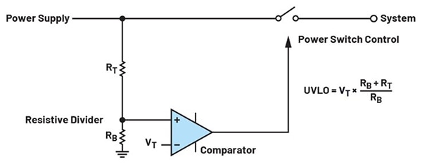
Supervisory circuits monitor system activity by tracking the voltage supply or using watchdog timers to detect inactivity, or both. When these safeguards detect an issue, power cycling opens and then closes the path between the power supply and a downstream system, causing the microcontroller unit (MCU) to enter a reset process. An input switch on the high side of the circuit (Figure 1) is used to control power to the downstream electronic system.
However, it is vital to choose the right components and address potential challenges such as heat generation and switching noise that can result from the power cycling process.
Figure 1: An application circuit using a high-side switch to protect a downstream electronic system from errors during brownout conditions. (Image source: Analog Devices, Inc.)
However, it is vital to choose the right components and address potential challenges such as heat generation and switching noise that can result from the power cycling process.
High-side power switch
Power cycling can be used in various applications to improve system reliability and mitigate potential damage, including wireless transceivers, medical devices, smart home devices, power supplies, and consumer electronics.
Metal-oxide-semiconductor field-effect transistors (MOSFETs) are widely used in power cycling because they have low on-resistance, high switching speed, and high input impedance.
The output from the supervisory circuit can control the gate of the MOSFET, effectively turning it on or off to cycle the power. This method ensures optimal system reliability by allowing the system to reset and recover from unresponsive states.
Developers taking this approach have the option of using N-channel or P-channel MOSFETs, but many prefer a P-channel approach as the conditions and circuitry needed to turn them on and off are less complicated than with N-channel MOSFETs.
For a P-channel MOSFET, the gate voltage must be lower than the source voltage to turn it on, while with an N-channel MOSFET, the gate voltage must be higher than the source voltage to turn it on.
When an N-channel MOSFET is used as a high-side input switch, low gate voltage causes the switch to open and disconnect the power supply. While N-channel MOSFETs generally offer better efficiency and performance, in this context, additional circuitry such as a charge pump is required to generate positive gate-source voltage (VGS) to ensure the switch completely reconnects the power supply.
That additional circuitry is not required when using a P-channel MOSFET, which can be turned on by negative VGS, simplifying application design, although the tradeoff is higher on-resistance and lower efficiency.
Implementing a P-channel high-side switch
With the P-channel approach, the gate-source voltage for controlling the MOSFET must be lower than the supply by at least the gate-source threshold voltage VGS(th) to allow current to flow from the source to the drain. Another consideration is ensuring the voltage between the drain and source (VDS) operates within specified limits to ensure the device is not damaged.
When an active low supervisory circuit output is connected to the gate of a P-channel MOSFET, the OUT pin pulls the gate low when the specified threshold is exceeded, activating connectivity from the supply voltage to the load. When the voltage falls below the threshold, the OUT pin goes high, and the P-channel MOSFET is turned off, disconnecting the load from the supply.
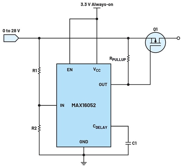
Developers can create an overvoltage protection circuit that is highly effective by directly connecting the OUT pin of the device to the gate of the P-channel MOSFET. This robust approach, using a P-channel MOSFET as a high-side switch connected to an Analog Devices, Inc., MAX16052 power management IC (Figure 2), ensures that the load is connected to the supply voltage.
Figure 2: A P-channel MOSFET is used as a high-side switch for overvoltage protection. (Image source: Analog Devices, Inc.)
An external pull-up resistor between the monitored voltage and the gate of the P-channel MOSFET keeps the gate high when the open-drain OUT pin is in a high impedance state. The OUT pin goes into a high impedance state when the monitored voltage exceeds the threshold, turning off the P-channel MOSFET and disconnecting the load from the supply voltage. Conversely, the OUT pin pulls the gate pin low when the monitored voltage falls below the threshold.
The MAX16052, along with ADI's MAX16053, comprise a line of small, low-power, high-voltage monitoring circuits with sequencing capability, both available in a compact 6-pin SOT23 package. The MAX16052 provides active-high open-drain output, while the MAX16053 offers an active-high push-pull output. Both provide adjustable voltage monitoring for inputs down to 0.5 V and perform voltage monitoring using a high-impedance input (IN) with an internally fixed 0.5 V threshold.
Employing a watchdog timer
Watchdog timers (WDTs) can enhance the protection capabilities of supervisory circuits in cases where the output signal is low when the monitored condition is met. In those circumstances, a watchdog timer can detect the lack of a pulse or transition for a certain amount of time, referred to as watchdog timeout (tWD), and activate a microcontroller reset or initiate a power cycle.
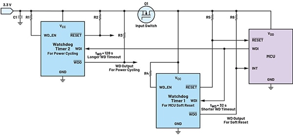
ADI's MAX16155 nanoPower supervisor with watchdog timer initiates a reset output when the positive supply voltage (VCC) exceeds the minimum operating voltage, even though it is less than the reset threshold. An application that utilizes two WDTs (Figure 3) can enable a microcontroller soft reset after 32 s of inactivity, and a system power cycle after 128 s of inactivity.
Figure 3: In this configuration Watchdog Timer 1 would activate a soft reset while Watchdog Timer 2 would initiate a system power cycle. (Image source: Analog Devices, Inc.)
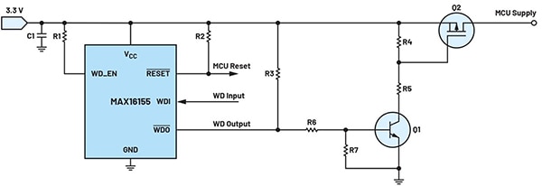
One option for driving a P-channel high-side switch is using an NPN bipolar junction transistor (BJT) as an inverter to convert a low signal from the watchdog output, which turns off the NPN transistor, into a high signal that turns off the P-channel MOSFET via a pull-up resistor. (Figure 4). When the system is active, the watchdog output (WDO) is high, sending its signal through a resistor to the base of the NPN transistor, turning it on.
Figure 4: An NPN bipolar junction transistor (Q1) drives the P-channel MOSFET (Q2). (Image source: Analog Devices, Inc.)
A resistor divider connected to the MOSFET’s gate and source controls the VGS. When the NPN transistor is on, it pulls the resistor divider low making the gate voltage lower than the source voltage, turning the P-channel MOSFET on to provide power supply to the system.
If the microprocessor becomes unresponsive or fails to send input pulses within the MAX16155 watchdog timer’s predefined timeout period, a watchdog timeout event occurs, causing the WDO pin to assert low. This action pulls the base of the NPN to ground, turning it off. When the NPN transistor is off, the voltage at the gate and source of the P-channel MOSFET is the same, turning the MOSFET off and cutting power to the microprocessor.
Once the watchdog timer’s WDO output returns high, the system resumes normal operation. The microprocessor then sends regular pulses to the WDI pin, preventing further timeouts. The NPN transistor turns on, keeping the high-side MOSFET on and ensuring continuous power to the microprocessor.
The low cost of bipolar junction transistors is a design advantage for P-channel high-side switches but requires proper tuning with the help of additional external components such as resistors.
Driving circuit using an N-channel MOSFET
Using an N-channel MOSFET to control a high-side P-channel MOSFET has several advantages over a bipolar transistor.
The N-channel MOSFET has low on-resistance, which reduces power loss and increases efficiency. It also switches quickly, improving system response times. It has lower switching losses and can operate at higher frequencies, making it ideal for energy-efficient applications like battery-powered devices. Also, gate-drive requirements are less demanding than those of a BJT, simplifying the driving circuitry and reducing the number of components.
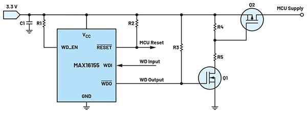
The watchdog output can directly control the gate of the N-channel MOSFET. The WDO’s pull-up voltage must match the MOSFET’s gate threshold voltage (VGS(th)) to work correctly. When the system is active, a high WDO signal turns on the N-channel MOSFET (Q1 in Figure 5), which then turns on the P-channel MOSFET (Q2 in Figure 5), supplying power to the system. During system inactivity, a low WDO signal turns off Q1, which turns off Q2, cutting off the power supply.
Figure 5: An N-channel MOSFET (Q1) driving a P-channel MOSFET (Q2). (Image source: Analog Devices, Inc.)
Conclusion
Using an N-channel or a P-channel MOSFET to drive a high-side switch are both reliable methods for system power cycling. The P-channel approach with NPN bipolar transistor and additional components provides the lower-cost option, while the more costly N-channel approach is better for high-frequency switching. The developer's design preferences and the application requirements will dictate the optimal approach.
免责声明:各个作者和/或论坛参与者在本网站发表的观点、看法和意见不代表 DigiKey 的观点、看法和意见,也不代表 DigiKey 官方政策。