Closing Your Control Loop Efficiently in MCU-Based Designs
投稿人:电子产品
2015-06-25
Control loops are one of the most fundamental tasks performed by many MCU-based designs. Often these designs fail to take full advantage of the key features and peripherals available in modern MCUs to most efficiently implement closed-loop control systems. Timers and interrupt controllers are often used in these systems, but some other features, like DMA, advanced analog-to-digital converters, and specialized math functions are many times overlooked when implementing control systems.
This article will quickly review some of the key requirements for efficient MCU-based closed-loop control systems. Common techniques for increased efficiency will be illustrated using some example MCUs. Once you understand some of the common techniques for improving efficiency you can better look for the implementation that will optimally close your next control-loop design.
Control-loop basics
Control loops are key elements used in controlling dynamic systems. A dynamic system can be any mechanical or electrical system that has a relationship (typically modeled as a linear relationship) between the input and output. The output usually needs to be controlled in such a way as to stay within a desired operating “band”. For example, the automatic cruise control in a car is such a system, where the speed of the car is set at a desired level and a controller keeps the speed constant even if the car encounters a hill. The algorithm that controls the speed utilizes a control loop that applies an input (the pressure on the accelerator), measures the result (the speed) and adjusts the input as needed to maintain the speed at the desired level. A block diagram of a simple single input and single output control system, with a control loop, is shown in Figure 1 below.

Figure 1: Block diagram of a simple dynamic control system control loop.
In the above block diagram the input to the dynamic system results in an output. The output is measured by a feedback sensor and the measured output is compared to the reference (desired) input. If there is a difference, the resulting error is used by the system controller to modify the system input to bring the system output closer to the reference input. The system controller needs to be intelligent enough to avoid oscillations and other problems that can result from an incorrectly managed control system. The assumption that the dynamic system is linear (where the output is proportional to the input) is not as restrictive as you might think because many mechanical and electrical systems do operate in a linear fashion, or can be easily “biased” to operate within the linear region of a more complex transfer function.
Using MCUs to implement a control loop
It is easy to see why MCUs are the workhorse for implementing control systems. With the ability to sense, compute, and control a variety of inputs and outputs, all at very-high performance rates (in particular, at high-performance rates with respect to mechanical systems like motors) MCUs are a natural control element. In addition to the capabilities of the CPU, many of the intelligent peripherals available in MCUs make closing your control loop simple and efficient.
Control loops usually have a timing relationship between each adjustment of the dynamic system. This “loop time” determines how quickly adjustments can be made. If the loop time is too long in relationship to the system dynamics (the time varying nature of the controlled system) it will be difficult if not impossible to efficiently control the system output. Oscillations and “runaway” errors can accumulate, putting the system in danger of failing, perhaps in a very dramatic nature. In general, the faster the MCU can close the loop (process the output sensor, determine any reference error, and adjust the system input), the better.
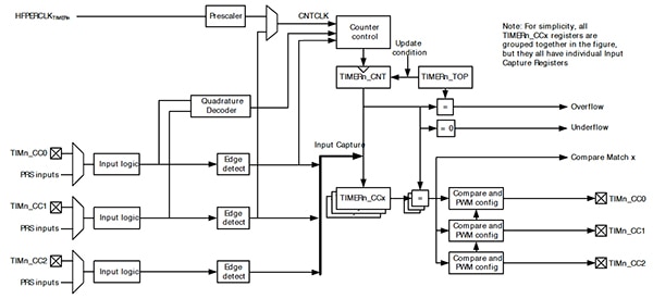
Efficient timing and counting are thus key functions needed to optimally close a control loop and MCUs with advanced timing peripherals can implement control loops optimally. For example, the Silicon Labs EFM32LG360F64G-E-CSP81 MCU has a timer/counter peripheral with several features useful in control-loop implementations. Often timing and counting are needed for functions in addition to the main loop timer of the closed-loop controller. Let's look at the block diagram of the EFM32LG counter/timer peripheral in more detail (Figure 2) to see how it can help implement other common functions within the control loop system shown in Figure 1.

Figure 2: Silicon Labs EFM32LG MCU timer/counter block diagram (Courtesy of Silicon Labs).
One useful feature of the Timer/Counter is the ability to count transitions from external sources via the TIMn_CCn pins on the left side of the diagram. These inputs can be helpful when observing sensors that produce transitions based on the measured output of the dynamic system. For example, rotational measurements based on position measurements often produce transitions on every revolution. Also notice there is a quadrature decoder block in the upper middle of the diagram that can be used for similar measurements. The number of counts recorded, when they reach a terminal value stored in Timern_TOP can be used to trigger an interrupt for immediate action or can be stored for future processing.
The timer/counter outputs, TIMn_CCn pins on the right side of the figure, can use a pulse-width-modulation (PWM) scheme common for controlling inputs to dynamic systems. In these systems the time the signal is active relates to a desired voltage or current level used for control. Precise control over the signal period, signal high time, and the edge transition points are all critical and can be efficiently controlled within the PWM features of the timer/counter. Having three separate PWM outputs is also convenient for common motor-control applications where three separate windings are used to vary the magnetic field associated with spinning the motor.
Intelligent peripheral control
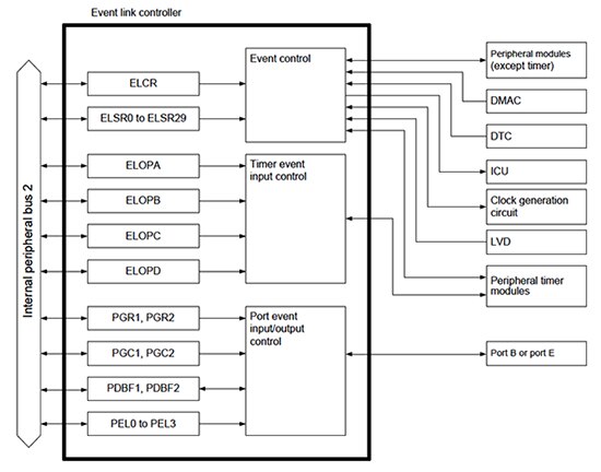
Achieving a fast and efficient loop feedback time often requires the use of intelligent peripherals to offload processing from the high-power CPU and program memory blocks. If peripherals can operate independently from the CPU, this can allow the CPU to do other more complex processing tasks or even to wait in a low-power state until processing is required. Some advanced MCUs have special peripheral control systems that can be used to configure autonomous operations by connecting peripherals together so no intervention from the CPU is required. For example, the Renesas R5F52108CDFM MCU, a member of the RX210 MCU group, has an Event Link Controller (ELC) that connects and controls peripheral outputs to peripheral inputs for autonomous operation. A block diagram of the ELC is shown in Figure 3 below.

Figure 3: Renesas RX210 group MCU event-link controller block diagram (Courtesy of Renesas).
The internal peripheral bus, on the left of the diagram, is used to interconnect peripherals, shown on the right side of the diagram. All of the peripherals, including the DMA controller, Data Transfer Controller (DTC), and Interrupt Controller Unit (ICU) can connect with specialized controls to autonomously activate peripherals based on interrupts, timer compare results, or pin transitions. As many as 59 types of event signals can be linked to peripherals to initiate conversions, start timers, and begin DMA or DTC transfers or any other desired peripherals. When an event that has been set as a trigger occurs, the operation set for the selected module is initiated.
Chains of multiple operations can be initiated so that complex operations can be done without CPU intervention. For example, a timer could initiate an analog-to-digital conversion and the converted value stored in memory. A counter could keep track of the number of conversions and the CPU could be interrupted when the count indicates a full data set is available for processing. The clock oscillator could be switched to a faster mode during CPU processing automatically as well. By using the ELC to its fullest, many of the sensing functions required in common control loops can be done very quickly and efficiently making it easy to achieve fast loop times while keeping power to a minimum.
Efficient computation
As we have seen, the use of intelligent and autonomous counter/timers and peripherals can improve loop times and reduce power consumption – both important aspects in control-system designs. Often, computations are required in each of the main control-system blocks to process the data needed when sensing, comparing, controlling, and operating the system being controlled. In fact, computation requirements increase dramatically as control-system efficiency, precision, and long operating lifetimes have become important system requirements. Advanced algorithms for implementing control loops now use proportional integral derivative algorithms where floating-point calculations are often needed for increased precision. If advanced calculations are not supported in hardware, control-loop closure at the required frequency becomes very difficult to achieve.
MCU manufacturers understand the need for advanced processing capabilities and have included numerical processing capabilities even on low-end MCUs that can speed the computations required for complex closed-loop control designs. High-end MCUs typically include dedicated hardware to speed floating-point computations required for the most precise control applications. The Freescale Kinetis K60 MK61FN1M0VMD15 MK61FN1M0VM class of MCUs uses the 32-bit ARM Cortex-M CPU with DSP instructions and a single-precision floating-point unit to speed the advanced computations needed for the most complex control algorithms. The DSP instructions include extended single-cycle multiple-accumulate (MAC) instructions for fast processing of high-precision signals, and single-instruction multiple-data (SIMD) instructions for faster processing of lower resolution signals. A hardware divide block operates in just 2 to 12 cycles, speeding common scaling operations.
For even more performance, a dual-core CPU can be used so that processing tasks can be done in parallel. For example, a Texas Instruments Concerto microcontroller, such as the F28M35H52, has both an ARM Cortex-M3 32-bit CPU and a Texas Instruments TMS320C28x 32-bit CPU with floating-point capability. A block diagram of this dual core MCU is shown in Figure 4 below.

Figure 4: Texas Instruments F28M35x Concerto MCU block diagram (Courtesy of Texas Instruments).
The ARM-based MCU, in the upper portion of the diagram, can be used for managing peripherals while the Concerto CPU can be used to process data and manage the system under control. Notice that the PWM timers are tied closely to the Concerto subsystem making it easy to generate the complex waveforms required by the inputs to the controlled system. This type of specialization between dual-core CPUs can be important to look for when your application has easily separable algorithms. If you just need more processing power for a single algorithm or require dual CPUs to operate in lockstep for higher reliability, a homogeneous dual CPU, with identical processing subsystems, like the Texas Instruments Hercules RM4 ARM Cortex-R4 MCU may be a better fit. Closed-loop control systems for high-reliability applications can use the built-in redundancy of a heterogeneous dual-CPU implementation for a more efficient and robust design.
Conclusion
Closing your control loop efficiently in MCU-based designs need not be fraught with trial-and-error approaches for finding an optimal implementation. A more systematic approach that uses all the advanced features of modern MCUs correctly can help you create more efficient, faster, lower power, and more cost-effective control-system solutions.
For more information about the parts discussed in this article, use the links provided to access product pages on the DigiKey website.
免责声明:各个作者和/或论坛参与者在本网站发表的观点、看法和意见不代表 DigiKey 的观点、看法和意见,也不代表 DigiKey 官方政策。


 中国
中国