Antennas: The Critical Link for High-Speed Wireless Networks
投稿人:电子产品
2014-04-24
Whether you are designing a handset, tablet, laptop, wireless router, or base station, the antenna (or antennas) that you select plays a critical role in the signal chain, determining the performance that the system will deliver. This choice becomes even more critical as data rates escalate beyond 1 Gbit/s, where even short gaps in the received signal stream could result in the loss of large amounts of data. In these systems, some run a single transmit/receive channel, while others employ multiple-input/multiple-output (MIMO) radio systems, beamforming techniques, and channel bonding to get the range and bandwidth needed to handle data rates ranging from hundreds of megabits to over 1 Gbit/s. These techniques, coupled with optimized antennas, ensure that the transmit and receive paths deliver every last microvolt of RF signal.
In any wireless system, there are several key performance metrics that can be adjusted to optimize the wireless network for the application. These metrics include:
- RSSI – Radio Signal Strength Indication – How strong is the received signal (antenna gain, low-noise amplifiers and power amplifiers all play a role in maximizing signal strength).
- SNR – Signal to Noise Ratio – The power ratio between the signal (useful information) and any background noise (the unwanted signal).
- Packet Delivery – An indicator that a message was sent and received. Typically greater than 50 percent is solid as the data is spread out across a spectrum.
- Receivers’ Sensitivity – A negative number of –83 dBm or greater is common. The more negative the number, the better the sensitivity. Every time the receiver sensitivity drops by a factor of –3 dBm, the receiver’s ability to detect the incoming signal improves by a factor of two.
- LOS (line of sight) – This refers to the distance that two radio frequency (RF) transceivers can visibly see each other without obstruction. This is important when estimating the range (distance) that separates two transceivers. Obstructions such as walls, trees, buildings, and others reduce the distance the two devices can be separated and still maintain the desired data transfer rate. Techniques such as MIMO and beamforming can improve the signal’s ability to get through.
- Diversity – In many wireless transmission systems the signal takes multiple paths (multipathing) to reach the receiver due to signals bouncing off various structures. The bouncing causes a slight delay in the signal reaching its intended destination, resulting in multiple copies of the signal reaching the receiver. The receiver must be able to select the best signal to amplify and also filter out the remaining copies.
However, there are two significant issues when using internal antennas in hand-held devices. Antenna volume is the first concern: the size of the antenna is determined by the frequency at which it is designed to operate. Thus, the handheld device needs a dedicated space inside its housing for an internal antenna or multiple antennas. Usually the space is limited, so smaller antennas are always desirable. The second issue is the potential interference between the antenna and its surroundings. This can include the interference from RF components/circuits in the handset, the case itself, and even someone holding the handset or other device.
For handsets, tablets, and other portable devices, some antennas can be deposited right on the system’s main printed circuit board or on the inside of the product’s case, while others are prefabricated on small surface-mountable chip-scale substrates that are, in turn, mounted on the product’s main circuit board. Additionally, the multiple radios used in handsets for Wi-Fi, Bluetooth, the cellular network, GPS, and still other wireless standards typically share one or more antennas that are switched between the different power amplifiers when transmitting and the low-noise amplifiers on the receive side.
One example of a ceramic chip antenna, the 5400AT18A1000E series from Johanson are passive, surface-mount components fabricated on a low-temperature co-fired ceramic technology (Figure 1). The antenna has a frequency range spanning 4,900 to 5,900 MHz, has a linear polarization and near-omnidirectional radiation pattern, and is matched to a 50 Ω impedance. Measuring just 3.2 mm long by 1.6 mm wide and just 1.3 mm thick, the antenna can be squeezed onto tightly packed circuit boards.

Figure 1: Designed for surface mounting, this co-fired ceramic antenna (magnified view shown here) from Johanson Technology actually measures just 3.2 x 1.6 x 1.3 mm and has a frequency range of 4,900 to 5,900 MHz.
Multiband chip antennas are also readily available. For example, the ANT016008LCD1575MA1 from TDK handles the GPS band with a center frequency of 1,575 MHz, and the ISM band centered at 2,442 MHz (Figure 2). The antenna has a linear polarization and a VSWR of 4, while presenting an impedance of 50 Ω. Taking up even less board space than the single-band antenna from Johanson, the TDK antenna is just 1.6 x 0.8 x 0.4 mm.

Figure 2: A multiband chip antenna, the ANT016008LCD1575MA1 from TDK handles both GPS and 2.4 GHz ISM frequency bands, yet measures just 1.6 x 0.8 x 0.4 mm.
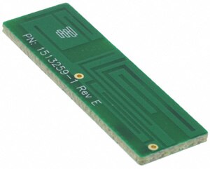
If the system has enough space, even antennas fabricated on a PCB can be used. This solution might be more appropriate for wireless routers, laptops, and other larger wireless devices. One example of the PCB antenna comes from TE Connectivity, a quad-band solution (designated 1513259-1) that measures 37.59 x 11.94 x 1.57 mm and works over the 824 to 960 and 1,710 to 1,990 MHz bands (Figure 3). The antenna has a VSWR of less than 3, linear polarization, and a peak gain of +1 dBi.

Figure 3: A quad-band antenna implemented on a small printed-circuit board from TE Connectivity handles the 824 to 960 and 1,710 to 1,990 MHz bands for both the U.S. and European standards.
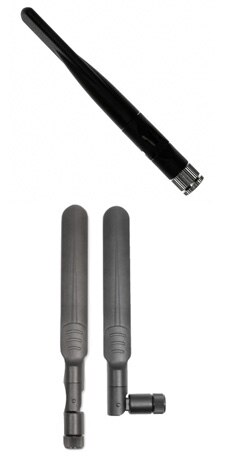
Although internal antennas can deliver solid performance, there are applications that demand higher gain and configuration flexibility by using external stick-like antennas such as the Linx Technologies ANT-DB1-RAF series dual-band half-wave antenna that covers the 2.45 and 5 GHz frequency bands (Figure 4a). The antenna includes a tilt and swivel joint that allows it to be oriented to optimize the reception or transmission. Offering a slightly different physical appearance, the W1043 multiband antenna from Pulse Electronics also operates over the 2.4 and 5 GHz ISM bands (also 5.15 and 5.85 GHz), making it compatible with IEEE 802.11a/b/g/n, Bluetooth, and ZigBee standards, as well as other ISM frequency-band applications (Figure 4b). Both the Linx and Pulse antennas have an omnidirectional radiation pattern that provides broad 360° coverage.

Figure 4: Dual-band antennas such as the ANT-DB1-RAF from Linx Technologies (a, top) and the W1043 from Pulse Electronics (b, bottom) are designed for external use and are commonly used on network routers, access points, and other systems that require broad coverage areas.
In summary, the antenna is the heart of a wireless system in that the performance of the system is closely tied to the antenna’s performance. Its basic function is to transmit and receive electromagnetic waves in a specific frequency band or bands. This article reviewed the options available to engineers tasked with deciding which antenna might be most relevant for the application and system configuration options available. For more information on the parts discussed, use the links provided to access product information pages on the DigiKey website.
免责声明:各个作者和/或论坛参与者在本网站发表的观点、看法和意见不代表 DigiKey 的观点、看法和意见,也不代表 DigiKey 官方政策。


 中国
中国