A Designer's Guide to Encoders
投稿人:Convergence Promotions LLC
2012-04-19
An encoder is a device that returns position information to a circuit. They can be made from one of several different technologies (e.g., mechanical or optical) and can provide a bewildering variety of output data.
Typical applications include systems that must sense the position of a moving part or rotating shaft. They are commonly used when a force actuator – like a motor – moves a part, providing feedback to tune the part’s position. Stepper motors, of course, move in precise steps so software can infer position, but other actuators do not and exhibit over- and under-shoot. They also usually vary in precision depending on the applied load. Without an encoder, the system software has little idea where a part is at any time.
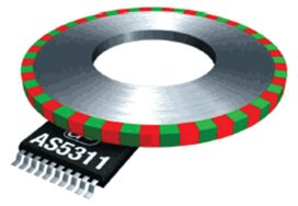
Optical and magnetic encoders use codewheels to sense position. These are disks that either contain a series of “windows” through which a light source can shine or a sequence of magnetic poles on the disk’s outer edge. Figure 1 shows a typical configuration using ams’ AS5311. Figure 2 shows the arrangement of an optical codewheel.


Figure 2 also introduces some terminology often used when specifying encoders. The first is ROP, or optical radius. This is the distance from the center of the codewheel to the line that runs through the middle of the windows. CPR, or codes per revolution, gives the number of unique positions the encoder can measure. This number can be as low as four for simple mechanical encoders, which gives a resolution of 90 degrees, to over 100,000 counts per revolution. Lines per inch (LPI) or lines per mm (LPM) are the resolution of a linear encoder.
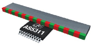
Traditionally encoders were differentiated by whether they sensed rotary or linear motion. The former was usually used to detect shaft angle. Today different products for linear or rotary are available, but some optical and magnetic encoders can be used in either application. Note how the same encoder is used in either application in Figure 1 and Figure 3. In linear applications, the codewheel is replaced by a codestrip.

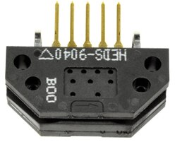
Encoders can be “housed” or enclosed in a package, as in Figure 4, or supplied as a module. An example of the former is Avago’s HRPG-ASCA; Avago’s JED-9040, shown in Figure 5, is an example of the latter. Modules come without a codewheel or codestrip.


Though codestrips are widely available commercially, some users fabricate their own to meet special needs. For example, monochrometers sometimes use narrow-pass band interference filters that spin. As the filter tilts, the center wavelength shifts, but it changes proportionally to the sine of the angle of rotation. To linearize the data, one can build a codewheel with windows spaced apart by the sine of the angle. The software reads a datapoint every time an encoder pulse occurs; with non-linear window spacing, each datapoint is separated by the same amount in the frequency domain.
Encoders come in four flavors: mechanical, optical, magnetic, and capacitive.
Magnetic encoders
Mechanical encoders use contacts that drag across strips on a substrate or PC board. As the shaft rotates, different connections are made, returning binary data indicating the shaft angle. These use very simple interfaces and are inexpensive. Lifetime is lower than other alternatives, ranging from around 15 K cycles to a maximum of around one million. They are commonly used as knobs for human interfaces. Many are available with detents to improve the knob’s feel.
The resolution runs from about four CPR up to 36 CPR. An example of the former is Honeywell Sensing and Control’s 510E1A48F204PB. Grayhill, Inc.’s 25LB10-Q exemplifies the latter.
Optical encoders
An optical encoder shines an LED through the windows in a codewheel or codestrip. Extremely-high CPRs are available, and some vendors will custom-build units with CPRs over one million.
Optical units – like magnetic and capacitive encoders – offer very long life, some rated to 300 million cycles. Many have no rating as the only moving part is the shaft whose position is being measured.
Unhoused units will degrade quickly in dirty environments, as the window sizes are very small for high-resolution units.
Magnetic encoders
Magnetic encoders use the Hall Effect to detect the poles on a codewheel or codestrip. They are increasingly popular since the entire encoder can be made as a single integrated circuit, and can be used in a range of configurations. Figure 1 and 3 are examples. Some units, like ams’ AS5030, need only a single two-pole magnet to provide 256 CPR as shown in Figure 6. The entire encoder is included in a tiny 16-pin TSSOP package.

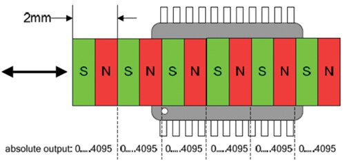
Magnetic units also offer very high CPRs and LPIs. The previously-mentioned ams’ AS5311 can resolve to 488 nm over a 2 mm distance. Figure 7 shows a typical configuration. For each pole pair, the encoder resolves 4096 counts.

Magnetic encoders, like their optical counterparts, have bandwidth limitations. For the AS5311 the maximum speed is 650 mm/sec. That’s over 1.5 million datapoints per second.
Magnets must be very close to an encoder, typically under a millimeter; some require the proximity of one third of that.
While mechanical and optical encoders guarantee absolute accuracy, magnetic versions do not. Accuracy degrades as the magnet’s distance from the encoder increases. Outputs may exhibit small amounts of hysteresis as the direction of travel reverses. Errors increase considerably if the pole length changes. Non-linearity for high-resolution encoders may exceed the rated CPR/LPI, so one must read the datasheets carefully.
Capacitive encoders
Capacitive encoders are the final type and are a relatively new technology; at this writing CUI Devices is the only vendor. These are all rotary devices; an assembly spins inside of the encoder’s body. Quite a bit of electronics is used to sense varying capacitance. In fact, these even include a microprocessor to initialize and zero the readings.
Though more expensive than some of the alternatives, capacitive encoders are much more rugged and are quite insensitive to environmental particulates and magnetic interference. With no LED to burn out (LED lifetimes are 100,000 to one million hours) it is claimed the capacitive versions have twice the lifetime of an optical unit.
An example is CUI Devices' AMT303-V, which is available with CPRs ranging from 96 to 1024, at up to a blistering 17,000 RPM.
This is a relatively new technology, so it is not a bad idea to get the development kit to become familiar with the products.
Outputs
In the past, encoders offered either a binary number representing position or a series of pulses. Now there are a wide range of options, and these options divide encoders into their two primary categories: absolute and incremental. Some bridge the gap and provide incremental data at high speed, and absolute numbers over a slower serial bus.
An absolute encoder returns position data encoded into a binary bit stream. Read a single position and you will know exactly how many counts the encoder is away from zero. It is like reading a GPS. Absolute models are easy to use, but it is hard to get over about 1000 CPR.
Incremental encoders are more like the speedometer. It is possible to infer position, but one has to accumulate data from when the car – or encoder – started moving. Instead of providing position, the encoder gives a pulse whenever the device moves one count. Therefore there is always an index pulse that signals when the encoder is at the zero position; by counting the pulses after seeing index asserted, one can calculate position.
Though it is more complex to use an incremental encoder, much higher CPRs can be achieved and pins counts are lower.
You would expect that an absolute encoder would return a binary number indicating position. Many do, though sometimes the datasheets refer to “hex” or “octal” to mean binary. Others produce BCD. Some return Gray code wherein only a single bit changes between counts. The sequence from 0 to 7 is 000, 001, 011, 010, 110, 111, 101, 100. This is much more reliable than binary in mechanical encoders.
Some encoders provide pulse-width modulated (PWM) outputs. The device issues a pulse stream with a duty cycle proportional to absolute position. For example, the already-mentioned AS5030 puts out a series of pulses with a 2.26 µsec “one” and 578.56 µsec “low” at position 0 and the opposite at just under 360 degrees. Feed this into a timer capture on a microcontroller and the software can easily compute position. The advantage of PWM is that, other than power and ground, only a single connection to the encoder is needed. That becomes especially important in high-noise or remote applications, since the output can be fed to a differential signaling circuit that eliminates common-mode noise.
Incremental encoders do not provide absolute position data, but instead offer other forms of output. The already-mentioned index pulse signals the zero position. Depending on the application, the software may have to park the system at zero to establish the initial readings when the system starts up.
The most common incremental output is called “quadrature,” in which the encoder outputs a pair of signals that are 90 degrees out of phase. Since the output is simply a pulse stream, there are fewer limits to the speed that can be achieved, so higher CPRs, even as the encoder rotates quickly, are possible. With only two outputs plus the index pulse, it is reasonable to use differential drivers in noisy environments.
The two quadrature outputs are simply square waves. The relationship of the two indicates direction, so if channel A leads B by 90 degrees, the encoder is spinning in one direction. If B leads, it is rotating the other way. Though in low-speed and low-CPR it is possible to feed these to GPIO inputs on a microprocessor, the CPU will quickly bog down trying to keep up with the pulses as speed increases.
A better approach is to tie either the A or B output to an interrupt request pin and the other to a GPIO input. The interrupt handler then samples the GPIO to determine which direction the encoder is rotating while summing interrupts to determine position. The index input goes to a different interrupt to zero out the sum. It is important to compute the interrupt rate to be sure the processor can keep up with the high number of interrupts per second, which will strain even the biggest CPU.
Alternatively, a bit of logic can differentiate the phase relationship of channels A and B. In one direction the logic increments a counter on-board the microcontroller; in the other a different counter is incremented. The software takes the difference to determine position.
Some processors read quadrature input directly, and can do very sophisticated measurements, such as velocity, in their hardware. An example is NXP’s LPC4350.
A few vendors offer ICs that decode digital quadrature signals, an example being Avago Technologies’ HCTL-2032. It will convert quadrature inputs from up to two encoders to absolute position. The results are available on the 8-bit data bus connected to a GPIO port or CPU bus. Modules are available as well, such as Rabbit Semiconductor’s RCM4100.
Quadrature is not limited to digital signals; some encoders provide the same information via sine and cosine waves, which of course are 90 degrees out of phase. Though it is reasonable to feed these to A/D converters, data rates can escalate quickly. Sin/cos signals are best used in low-speed, low-CPR applications or those where the information is used by analog circuits. An example sin/cos encoder is ams’ AS5215.
Conclusion
Encoders have been around for a very long time, but in recent years an explosion of variants have appeared. Digi-Key lists nearly 2,000 different units, with practically any precision available. Modular units can handle an infinite variety of codestrips and codewheels. Even in remote, harsh environments, it is easy to return high-accuracy data to a processor. With the timers on board every microcontroller, or the use of interrupts or even external quadrature decoders, it has never been easier to interface to these essential position-measuring components.

免责声明:各个作者和/或论坛参与者在本网站发表的观点、看法和意见不代表 DigiKey 的观点、看法和意见,也不代表 DigiKey 官方政策。


