How To Control Servos using an Arduino or Raspberry Pi
2023-11-15 | By Maker.io Staff
Motors Servo Arduino Raspberry Pi

Another recent article discussed how servos differ from regular DC or AC motors and mentioned how to control a servo using PWM signals. This article dives deeper into the topic of controlling servos, and it explains how you can orchestrate servo motors in your projects using an Arduino or Raspberry Pi.
Recap: How Do Servos Work?
Controlling servos involves varying the pulse width of the PWM control signal within a specific range — for example, one to two milliseconds. The signal itself typically oscillates at a fixed frequency of usually 50 Hz. The pulse width determines the servo's angle, where the minimum width corresponds to zero degrees, and the maximum width makes the servo rotate to its maximum angle.
Controlling a Single Servo using an Arduino
Using the standard servo library, you can instruct Arduino boards to control servos without knowing the nitty-gritty details of pulse width modulation or hardware timers. The library translates a high-level angle into an appropriately modulated signal servo motors can understand. The standard library allows most Arduino boards to control up to twelve servos. Some devices, like the Arduino Due, can even control up to sixty servos.
To get started, connect the servo’s control signal line to a compatible pin on the Arduino board. Then, attach the servo motor to an appropriate power supply. Usually, servo motors operate on 5 V. Finally, connect the servo’s GND wire to the Arduino’s GND pin.
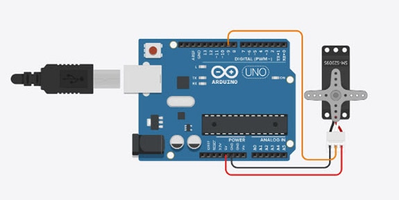
The following example uses an Arduino Uno with the servo’s control signal wire connected to GPIO pin nine:
 This image illustrates how to connect a simple micro-servo to an Arduino Uno board.
You can use the following example sketch to make the servo rotate between its minimum and maximum position in 30-degree increments:
#include <Servo.h>
#define SERVO_PIN 9

Servo servo;

void setup()
{
  servo.attach(SERVO_PIN);
}

void loop()
{
  for (int angle = 0; angle <= 180; angle += 30)
  {
	servo.write(angle);
	delay(250);
  }
}
The script starts with importing the servo library and defining the GPIO pin. Next, the program creates a servo object, of which there can be up to twelve on most Arduino boards. The setup function then links that object to the physical servo connected to pin nine of the development board.
The for-loop within the loop function initializes a new variable representing the servo angle, then increments this variable in 30-degree steps until it reaches 180 degrees, which is the maximum turning angle of the servo in this example. In each iteration of the loop, the Arduino sends the desired angle to the servo and waits a quarter second before advancing the motor.
Controlling Servos using a Raspberry Pi
Unlike Arduino’s standard servo library, there’s no equivalent for the Raspberry Pi that you can use to remove all low-level PWM calls from your code. Instead, you can use the Pi’s GPIO library standard functions to change the duty cycle of the servo motor’s control signal and make it rotate to the target angle.
To get started, connect the servo to the Raspberry Pi, as shown in the following Scheme-it design.
Next, create a new Python script with the following contents:
import RPi.GPIO as GPIO
import time

SERVO_PIN = 17
GPIO.setmode(GPIO.BCM)
GPIO.setup(SERVO_PIN, GPIO.OUT)

# Define GPIO 17 as a PWM output with a frequency of 50Hz and
# Initialize it with a duty cycle of 5%
pwm = GPIO.PWM(SERVO_PIN, 50)
pwm.start(5)

try:
  while True:
    for dutyCycle in range(5,11):
      pwm.ChangeDutyCycle(dutyCycle)
      time.sleep(0.5)
except KeyboardInterrupt:
  pwm.stop()
  GPIO.cleanup()
The above Python program first loads the necessary libraries and then defines a few variables. The first variable corresponds to the GPIO pin attached to the servo’s control signal. The script then initializes that pin before defining a second variable that represents the PWM signal. Next, the script endlessly loops through all numbers between five and 11 in increments of one, representing the control signal’s duty cycle in percent.
In this case, a duty cycle of five percent corresponds to a one-millisecond active time of the PWM signal, which makes the servo turn to its zero-degree position. Conversely, a duty cycle of ten percent represents the maximum turning angle of the servo. The program applies this duty cycle to the PWM signal and then waits half a second before moving on.
The program repeats these steps until you cancel it using Ctrl + C in the console. When the program receives this signal, it stops the PWM output and releases the Pi’s GPIO resource.
Summary
Servos differ from regular DC motors in many ways. For example, they include a gearbox and control circuit to allow for precise angular positioning using PWM signals.
Arduino boards can utilize a standard library to translate a high-level servo angle into a low-level PWM signal. Most Arduino development boards support up to twelve servos, while the Due can control up to sixty of these handy actuators.
Unfortunately, the Raspberry Pi doesn’t offer an equivalent default library you can utilize. While third-party libraries that remove the low-level calls are available, the standard method of controlling a servo using a Raspberry Pi includes directly modifying the control signal’s duty cycle.

Have questions or comments? Continue the conversation on TechForum, DigiKey's online community and technical resource.
Visit TechForum


 中国
中国